
Air inlet component, air filter and motor vehicle

A technology for air filters and components, which is applied in the field of motorcycle accessories, and can solve problems such as the complex structure of the air filter body, the inability to expand the gas, and the reduction of the noise reduction effect of the air filter.

Pending Publication Date: 2019-07-02
JIANGMEN DACHANGJIANG GROUP CO LTD
View PDF0 Cites 0 Cited by
  • Summary
  • Abstract
  • Description
  • Claims
  • Application Information

AI Technical Summary

Problems solved by technology

[0003] However, due to the limitations of the overall layout, performance and appearance of the motorcycle, the structure of the air filter body is complex and irregular, and it is easy to form a narrow flow rate dead zone in the air filter cavity, and it is also necessary to consider improving the air filter inlet. The internal dust-proof and water-resistant effects restrict the pipeline direction of the air filter intake system. At this time, once the air intake of the dirty cavity is designed in a narrow space, the high-speed airflow from After the intake cover of the air filter is sucked into the dirty cavity, due to the narrow space, the ratio of the expansion area of ​​the gas at the intake cross-sectional area of ​​the air filter intake cover to the interface of the dirty cavity of the air filter body is very small, so that the gas cannot be obtained. Sufficient and timely expansion, which greatly reduces the effect of air filter intake noise reduction, and finally shows that the suction noise is large when the motorcycle is idling, which affects comfort

Method used


Image

  • Air inlet component, air filter and motor vehicle
  • Air inlet component, air filter and motor vehicle
  • Air inlet component, air filter and motor vehicle

Examples


Embodiment Construction

[0034] In order to make the object, technical solution and advantages of the present invention clearer, the present invention will be further described in detail below in conjunction with the accompanying drawings and specific implementation methods. It should be understood that the specific embodiments described here are only used to explain the present invention, and do not limit the protection scope of the present invention.

[0035] It should be noted that when an element is referred to as being “fixed on”, “disposed on” or “installed on” another element, it may be directly on the other element or there may be an intervening element. When an element is considered to be "connected" to another element, it may be directly connected to the other element or there may be an intervening element at the same time; the specific way that one element is fixedly connected to another element can be realized through existing technologies, and will not be discussed here. To repeat it agai...


PUM

PropertyMeasurementUnit
Equivalent diameteraaaaaaaaaa
Wall thicknessaaaaaaaaaa

Abstract

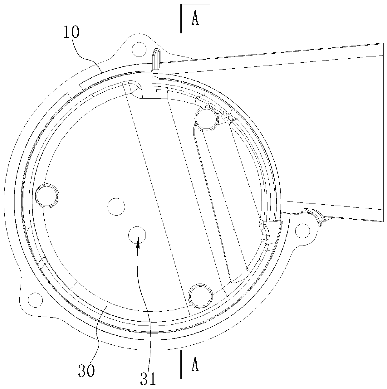
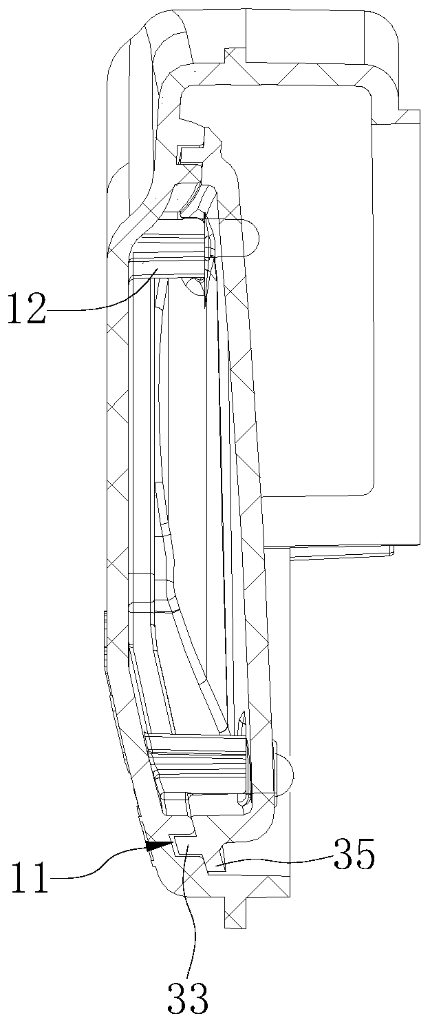
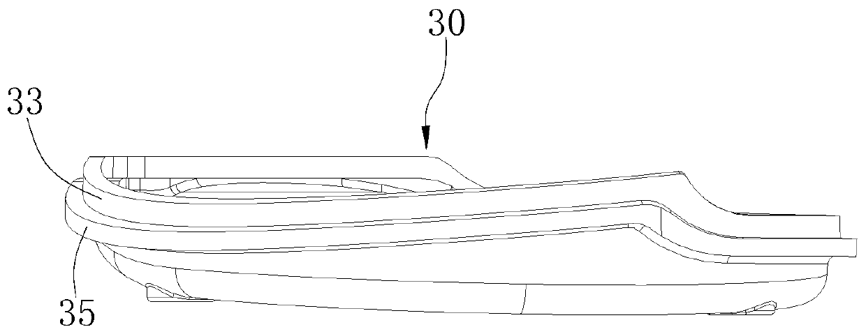
The invention relates to an air inlet component, an air filter and a motor vehicle. The air inlet component comprises an air inlet cover used for being arranged on an air filter body and a noise lowering cover used for being arranged on the inner surface of the air inlet cover in a sealed manner, wherein the noise lowering cover is provided with an air passing through hole, and the noise loweringcover, the air passing through hole and the air inlet cover are matched to form a noise lowering structure. Since the noise lowering cover is arranged on the inner surface of the air inlet cover in the sealed manner, the noise lowering cover divides a cavity between the air inlet cover and the air filter body into a first cavity and a second cavity, and the first cavity and the second cavity are in communication through the air passing through hole. Thus, in the air inlet process, the noise lowering structure is formed through cooperation of the noise lowering cover, the air passing through hole and the air inlet cover, the first cavity can effectively absorb pressure waves in the second cavity through the air passing through hole, gas located in the second cavity is sufficiently expandedin time, accordingly, the air absorbing noise can be lowered, and the comfort feeling and experience feeling during vehicle idling can be improved.

Description

technical field [0001] The invention relates to the technical field of motorcycle accessories, in particular to an air intake component, an air filter and a motor vehicle. Background technique [0002] The power system of motor vehicles such as motorcycles is mainly composed of the engine and the intake system connected to the engine. The intake system mainly includes the engine intake pipe, the throttle valve body, the air filter outlet pipe, the air filter body and the air filter intake cover (or Tube). During the intake stroke of the engine, fresh air enters from the air filter intake cover through the above-mentioned components until it enters the cylinder. For the engine air intake system, it is not only required that the air intake resistance should be small to ensure smooth gas flow, but also that the noise reduction and waterproof and dustproof functions should be good. In the air intake system, the air filter not only has the function of filtering air and preventi...

Claims


Application Information

Patent Timeline
IPC IPC(8): F02M35/12F02M35/14F02M35/16
CPCF02M35/1216F02M35/1255F02M35/14F02M35/162
Inventor 白清祥苏爱国高宏亮李杨
Owner JIANGMEN DACHANGJIANG GROUP CO LTD
Learn More