
Hydraulic control system and front rear-driving hydraulic automatic gearbox comprising system

A technology of hydraulic control system and hydraulic torque converter, which is applied in the direction of vehicle gearbox, transmission device control, transmission components, etc., can solve the problems of increasing manufacturing cost, increasing the structural size of the gearbox, and complex logic of the gearbox hydraulic control system. , to achieve the effect of improving shifting quality and saving costs

Pending Publication Date: 2019-07-02
南京劲力变速器科技有限公司
View PDF0 Cites 0 Cited by
  • Summary
  • Abstract
  • Description
  • Claims
  • Application Information

AI Technical Summary

Problems solved by technology

Considering that the gearbox is in the forward function state, in order to realize the engine braking function, the one-way clutch must also be considered ineffective in the design of the hydraulic control system, so the one-way clutch is mostly arranged in series with the brake or clutch, and the one-way clutch is in the shifting position. The layout in the box can be seen in detail Figure 5 (F0 / F1 / F2 are all one-way clutches), which makes the logic of the gearbox hydraulic control system complex, increases the overall structural size of the gearbox, and increases the manufacturing cost

Method used


Image

  • Hydraulic control system and front rear-driving hydraulic automatic gearbox comprising system
  • Hydraulic control system and front rear-driving hydraulic automatic gearbox comprising system
  • Hydraulic control system and front rear-driving hydraulic automatic gearbox comprising system

Examples


Embodiment Construction

[0018] The technical solutions of the present invention will be further described in detail below in conjunction with the accompanying drawings and specific embodiments.

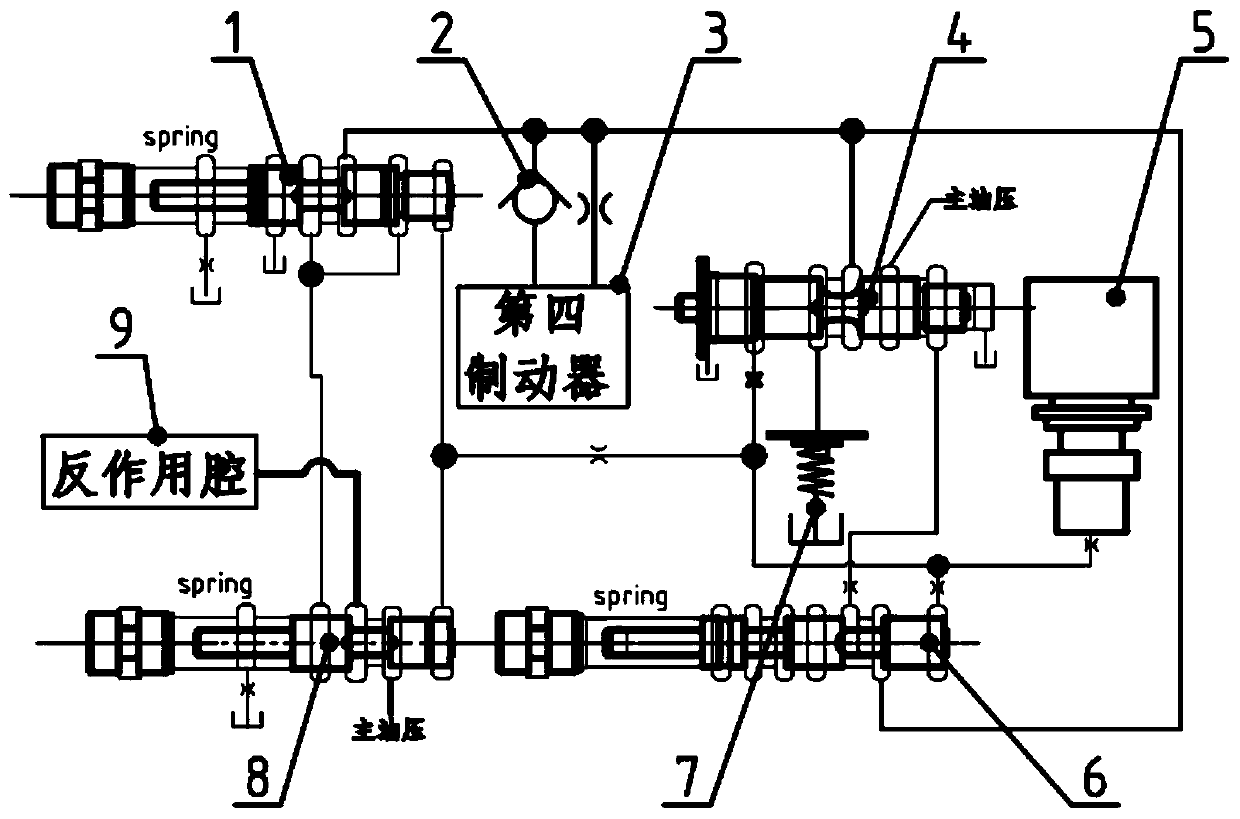
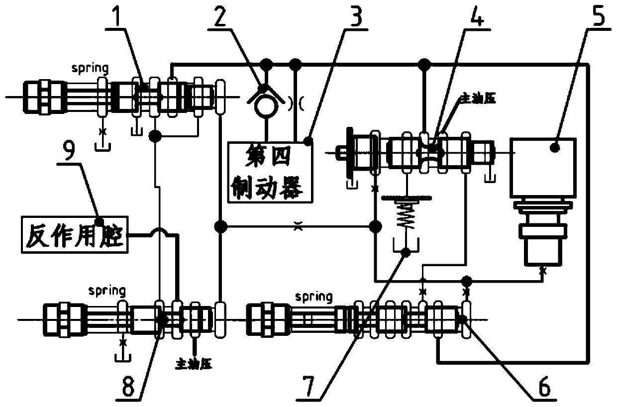
[0019] The hydraulic control system of this embodiment and the corresponding downshifting strategy, the hydraulic control system is composed of a high-pressure oil circuit, a gear switching oil circuit, a lock-up separation oil circuit and a lubricating oil circuit. The main functions of this hydraulic system are:

[0020] 1. By controlling the switching states of 5 hydraulic actuators (the first clutch, the second clutch, the third brake, the fourth brake, and the fifth clutch), the switching of P / R / N / D gears is realized, and the D gear is divided into D1 / D2 / D3 / D4 / D5 / D6 six gears.

[0021] 2. According to different working conditions, control the switching between the locking / unlocking states of the hydraulic torque converter. It is in the unlocked state when starting / climbing and other working conditions...


PUM


Abstract

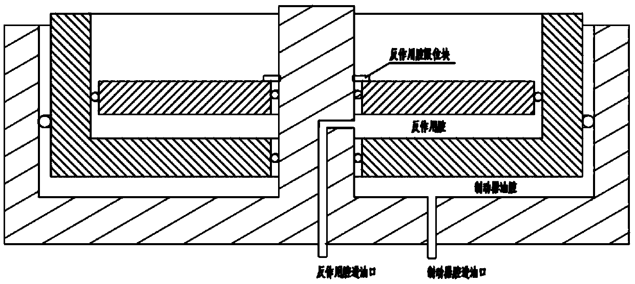
The invention discloses a hydraulic control system and a corresponding downshifting strategy. The hydraulic control system is composed of a high-pressure oil way, a gear shifting oil way, a locking and separating oil way and a lubricating oil way. Switching of a P gear, an R gear, an N gear and a D gear is achieved by controlling the on-off states of five hydraulic actuating mechanisms (includinga first clutch, a second clutch, a third brake, a fourth brake and a fifth brake), wherein the D gear comprises six gears including the D1 gear, the D2 gear, the D3 gear, the D4 gear, the D5 gear andthe D6 gear. Switching of two states including locking and unlocking of a hydraulic torque converter is controlled according to different working conditions. The hydraulic torque converter is in the unlocking state under the working conditions such as starting and climbing which need torque increasing and is in the locking state after a certain speed is achieved, and the high transmission efficiency is guaranteed. According to the hydraulic control system, the gear shifting impact problem generated when the second gear is decreased to the first gear is effectively solved, two oil cavities aresimultaneously controlled by one electromagnetic valve, and the cost is effectively reduced; and meanwhile, actions of the brakes and a counteracting cavity have the linkage, the hydraulic control system can better adapt to different working conditions, and the gear shifting quality can be effectively improved.

Description

technical field [0001] The present invention relates to automobile gearboxes, in particular to a novel hydraulic control system and a front-rear drive 6-speed hydraulic automatic gearbox including the hydraulic control system. Background technique [0002] The gearbox is an important part of the car when changing gears. Generally, the hydraulic control system on the gearbox is used to switch between high and low gears. Shift comfort is an important indicator of the gearbox. The existing automatic transmission hydraulic control system, in order to reduce the impact of shifting and improve the comfort of shifting when the gearbox is downshifting (especially when downshifting from 2 to 1), mostly adopts the structure of a one-way clutch. Figure 4 , the principle is that in the process of downshifting, since the speed of the engine remains unchanged and the vehicle speed is fast, the output of the transmission is used as the power source to input power in reverse, the one-way c...

Claims


Application Information

Patent Timeline
Patent Type & Authority Applications(China)
IPC IPC(8): F16H61/04F16H61/48
CPCF16H61/04F16H61/48F16H2200/0052
Inventor 薄其雷高玲玲武磊李雄飞王安龙
Owner 南京劲力变速器科技有限公司
Learn More