Automatic parking path planning device
A path planning, automatic parking technology, applied in the field of parking, can solve the problems of excessive curvature of the curve, the vehicle cannot keep up, the slope changes greatly, etc., to achieve the effect of satisfying kinematic constraints
- Summary
- Abstract
- Description
- Claims
- Application Information
AI Technical Summary
Problems solved by technology
Method used
Image
Examples
Embodiment 1
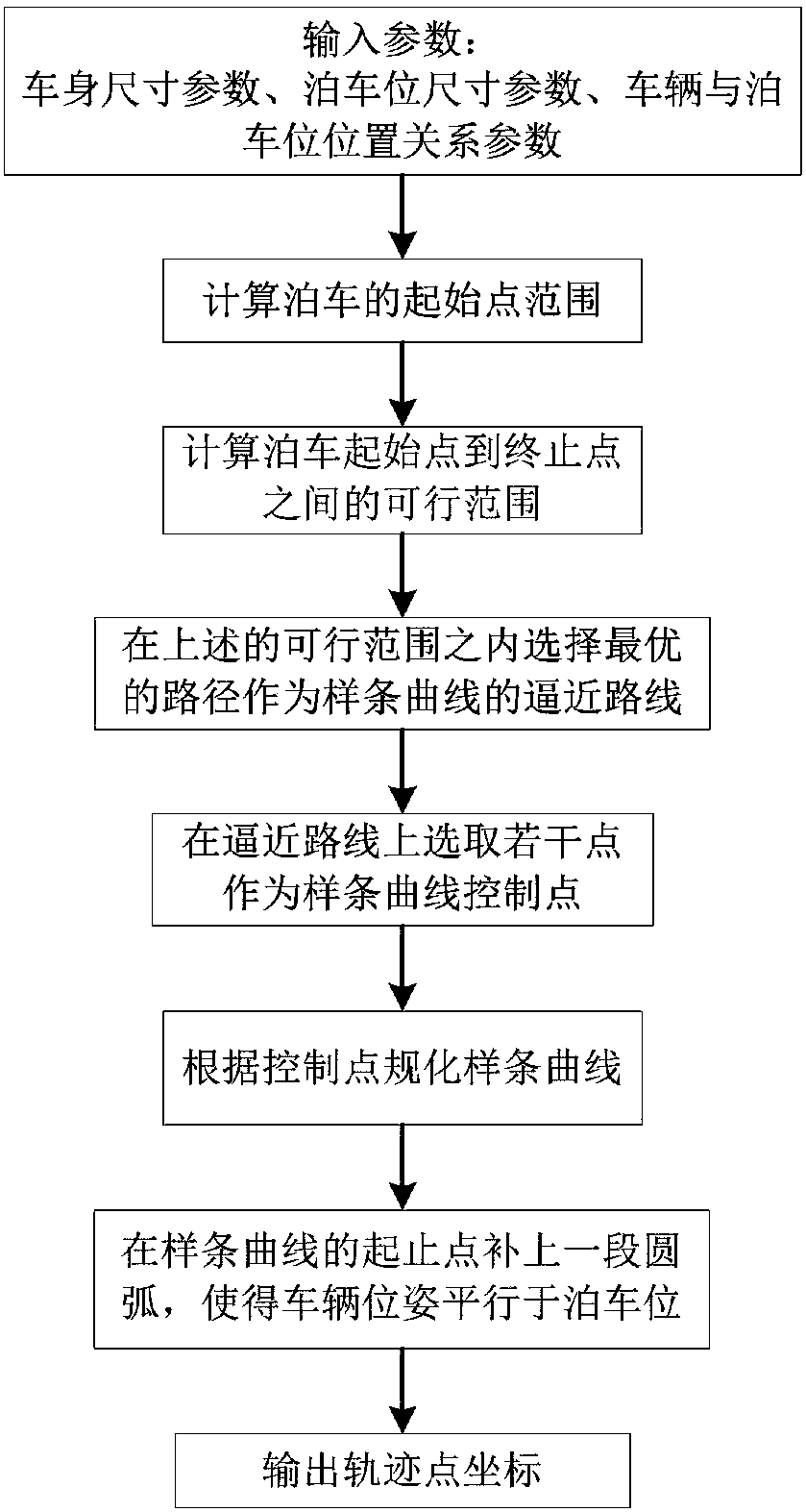
[0018] Embodiment 1: In the automatic parking control system, path planning, as a key core technology, has always been the focus and focus of many researchers. Good path planning can not only ensure the vehicle's obstacle avoidance function, but also reduce the pressure on the control execution system.
[0019] For parallel parking spaces, the method of double-arc splicing is the most basic method. This method calculates the initial position of the parking space through the relative relationship between the vehicle and the parking space, and then swings the vehicle into the parking space through an arc formed by two minimum turning radii. After relaxing the requirements, the radius of the two arcs can be extended to any radius that meets the vehicle kinematics, obstacle avoidance requirements, and tangency constraints. However, the parking path planning method based on arc splicing has an insurmountable difficulty, that is, the curvature is discontinuous. This requires the v...
Embodiment 2
[0064] Embodiment 2: A method for ensuring the position and attitude constraints of the starting point of the vehicle in automatic parking path planning, characterized in that a section of circular arc determined by the minimum radius of the vehicle is filled at the starting point of the spline curve, and the arc and At the contact points of spline curves, the first derivative is continuous, and the first derivative at the starting point of the arc is 0.
[0065] The arc completed at the starting point of the planned spline curve is the first arc segment. At the starting point of the spline curve, the position and attitude of the vehicle are respectively Xi_B, Yi_B, Thetai_B, and the right and upward are X The positive direction of the axis and the Y axis, the coordinates and poses of the starting point and the ending point of the first arc segment are obtained by the following formula:
[0066]
[0067]
[0068] According to the obtained start point and end point positi...
Embodiment 3
[0084] Embodiment 3: A method for ensuring vehicle kinematics constraints when straightening the vehicle body in automatic parking path planning, characterized in that a section of arc determined by the minimum radius of the vehicle is filled at the end point of the spline curve, the At the point where the arc and the spline curve meet, the first derivative is continuous, and the first derivative at the end point of the arc is 0. The circular arc completed at the end point of the planned spline curve is the second arc segment. At the end point of the spline curve, the position of the vehicle (that is, the x, y coordinates in the local coordinate system) and the attitude are represented by Xf_B, Yf_B, Thetaf_B represent, and, take rightward and upward as the positive direction of X-axis and Y-axis, then, at the end point of the spline curve, the starting point of the second arc segment (the point connected with the spline curve) and the position and attitude of the end point ar...
PUM
 Abstract
Description
Claims
Application Information
 - R&D
- Intellectual Property
- Life Sciences
- Materials
- Tech Scout
- Unparalleled Data Quality
- Higher Quality Content
- 60% Fewer Hallucinations
Browse by: Latest US Patents, China's latest patents, Technical Efficacy Thesaurus, Application Domain, Technology Topic, Popular Technical Reports.
© 2025 PatSnap. All rights reserved.Legal|Privacy policy|Modern Slavery Act Transparency Statement|Sitemap|About US| Contact US: help@patsnap.com


