Winding and scale construction for inductive position encoders

An encoder and winding technology, applied in the field of measuring instruments, can solve problems such as system limitations and achieve the effect of offsetting errors

Active Publication Date: 2021-06-29
MITUTOYO CORP
View PDF25 Cites 1 Cited by
  • Summary
  • Abstract
  • Description
  • Claims
  • Application Information

AI Technical Summary

Problems solved by technology

[0007] However, existing systems are limited in their ability to provide some combination of user-desired features, such as compact size, signal strength, high resolution, cost, physical layout, and robustness to misalignment and contamination, etc. combination

Method used


Image

  • Winding and scale construction for inductive position encoders
  • Winding and scale construction for inductive position encoders
  • Winding and scale construction for inductive position encoders

Examples


Embodiment Construction

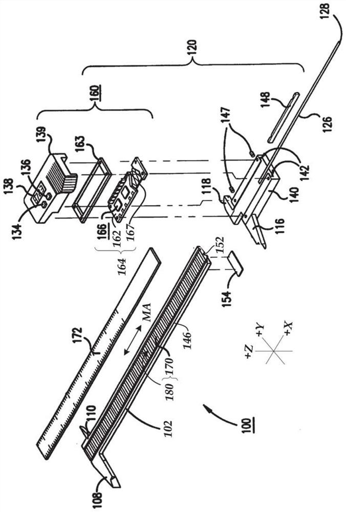
[0044] figure 1 is an exploded isometric view of a hand tool type caliper 100 including a scale member 102 having a generally rectangular cross-section including scale 170 and a slider assembly 120 . In various embodiments, the scale 170 may extend along the measurement axis direction MA (eg, corresponding to the x-axis direction), and may include a signal modulation scale pattern 180 . A cover layer 172 of known type (eg, 100 μm thick) may cover the scale 170 . Jaws 108 and 110 near the first end of scale member 102 and movable jaws 116 and 118 on slide assembly 120 are used in a known manner to measure the size of an object. The slider assembly 120 may optionally include a depth rod 126 retained by an end stop 154 ​​in a depth rod groove 152 below the scale member 102 . The depth rod engagement end 128 can be extended into the bore to measure its depth. Cover 139 of slider assembly 120 may include on / off switch 134 , zero set switch 136 and measurement display 138 . the ...


PUM


Abstract

A pitch compensation inductive position encoder includes a scale, a detector and a signal processing unit, the scale includes a first track and a second track with a periodic pattern with a wavelength of W. The second track pattern may be shifted by a pattern offset STO relative to the first track pattern in the measuring direction. In the detector, the first track field generating coil section and the second track field generating coil section generate fields in first and second inner regions aligned with the first pattern track and the second pattern track, respectively. The first and second sensing coil configurations respectively aligned with the first and second rails are offset relative to each other by STO + / −0.5*W in the measuring direction. In various embodiments, the first sensing coil configuration and the second sensing coil configuration may have the same order of individual coil polarities if the generated field polarities are different, or may have an inversion or the opposite if the generated field polarities are the same. Order.

Description

[0001] Cross References to Related Applications [0002] This application is a continuation-in-part of U.S. Patent Application Serial No. 15 / 850,457, filed December 21, 2017, and entitled WINDING ANDSCALE CONFIGURATION FOR INDUCTIVE POSITION ENCODER, filed August 24, 2016 15 / 245,560, entitled "WINDING CONFIGURATION FOR INDUCTIVE POSITION ENCODER," the disclosure of each of which is hereby incorporated by reference in its entirety. technical field [0003] The present invention relates to surveying instruments, and more particularly to inductive position encoders, which may be used in precision surveying instruments. Background technique [0004] Various encoder configurations may include various types of optical, capacitive, magnetic, inductive, motion and / or position transducers. These transducers utilize various geometries of transmitters and receivers in the readhead to measure movement between the readhead and the scale. Magnetic and inductive transducers are relativel...

Claims


Application Information

Patent Timeline
Patent Type & Authority Patents(China)
IPC IPC(8): G01D5/245
CPCG01D5/2451G01D5/2053
Inventor T.S.库克
Owner MITUTOYO CORP
Why Eureka
Try Eureka