Light guide plate applicable to polarized backlight and polarized backlight

A technology of light guide plate and backlight source, applied in the direction of light guide, optics, optical components, etc., to achieve the effect of improving uniformity and uniform and continuous polarized light

Inactive Publication Date: 2019-07-02
JIANGSU JICUI INTELLIGENT LCD TECH CO LTD
View PDF0 Cites 0 Cited by
  • Summary
  • Abstract
  • Description
  • Claims
  • Application Information

AI Technical Summary

Problems solved by technology

[0005] In the polarized backlight, the same type of LED light source is also used, so there is also the problem of horizontal uniformity adjustment

Method used


Image

  • Light guide plate applicable to polarized backlight and polarized backlight
  • Light guide plate applicable to polarized backlight and polarized backlight
  • Light guide plate applicable to polarized backlight and polarized backlight

Examples


Embodiment Construction

[0025] In the following description, for purposes of explanation and to have a comprehensive understanding of the present invention, numerous specific details are set forth, however, it will be obvious to those skilled in the art that the present invention can be practiced without these specific details. . In other instances, well-known structures and devices are shown in block diagram form. In this regard, the illustrative example embodiments have been presented for purposes of illustration only, and are not intended to be limiting of the invention. Therefore, the protection scope of the present invention is not limited by the above specific embodiments, but only by the scope of the appended claims.

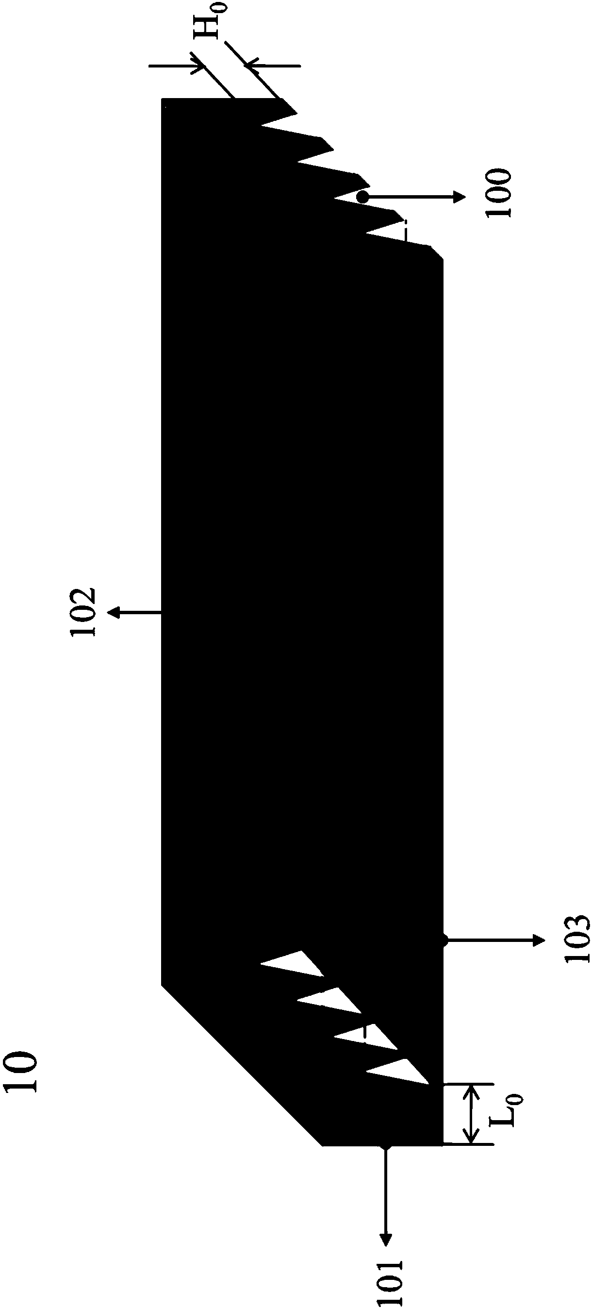
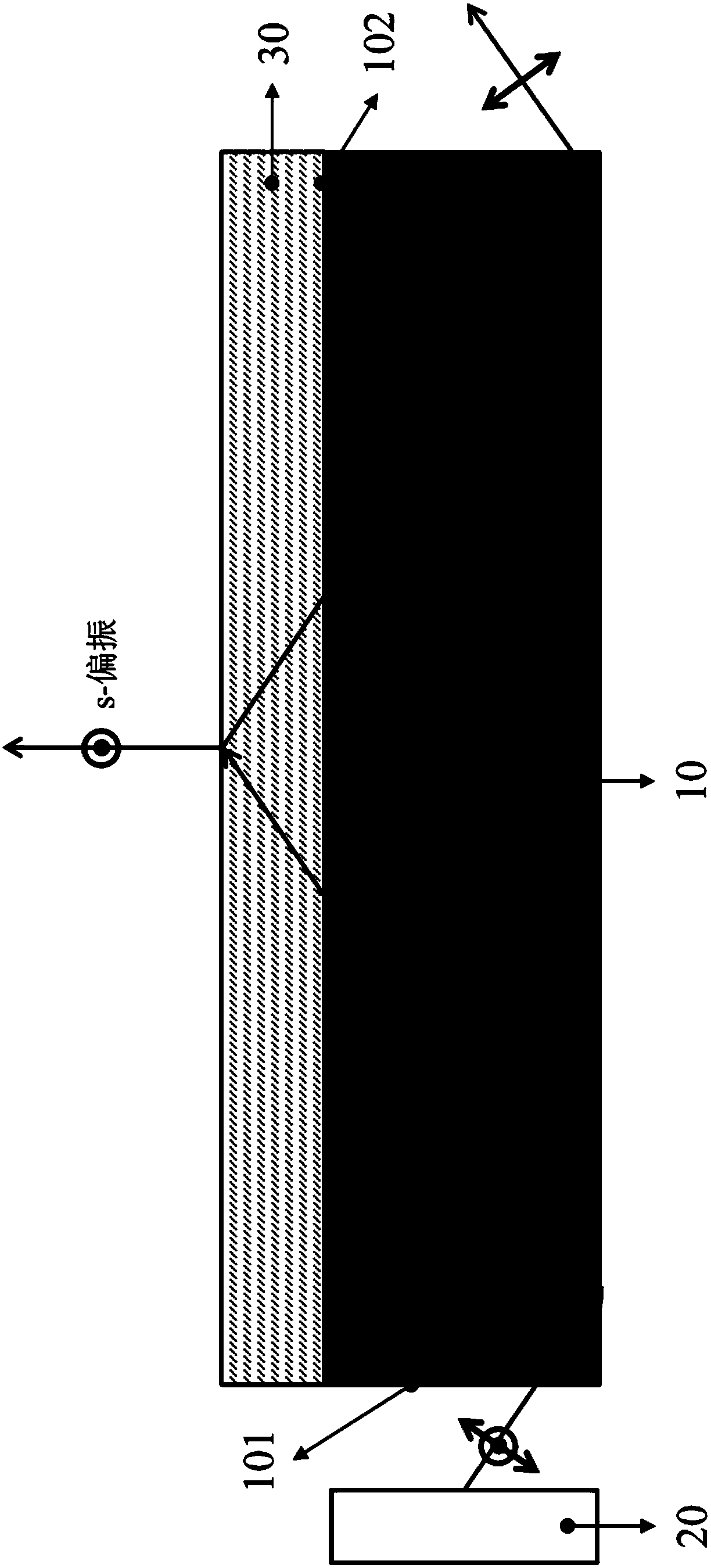
[0026] First refer to figure 1 , which shows a light guide plate 10 according to an embodiment of the present invention, which can be used for a polarized backlight. The light guide plate 10 includes a light incident surface 101, a light exit surface 102, a first surface 103, ...


PUM


Abstract

The invention relates to a light guide plate applicable to a polarized backlight and the polarized backlight. The light guide plate comprises a light incident surface, a light emergent surface, a first surface and a microarray, wherein the light emergent surface is connected to the light incident surface; the first surface is connected with the light incident surface and is basically parallelly with the light emergent surface; and the microarray is arranged on the first surface and comprises multiple parallelly-arranged micro structures, the micro structure extends along a direction vertical to the light incident surface, the microarray and the light incident surface are separated, and a gap exists. The light guide plate is configured to propagate natural light incident from the light incident surface in a total reflection mode. With the help of the laterally-distributed micro structures, the light guide plate can improve the uniformity of the polarized light emitted from the polarizedbacklight in the lateral direction.

Description

technical field [0001] The invention relates to the technical field of liquid crystal display, in particular to a light guide plate and a polarized backlight that can be used for a polarized backlight. Background technique [0002] Flat panel displays, such as liquid crystal displays (LCDs), are essential components of many types of electronic equipment. As a passive light-emitting device, a liquid crystal display relies on a backlight on the back of the display to illuminate the screen. Due to the display requirements of liquid crystal flat panel displays, the light that is effectively used is light with a specific polarization direction. For traditional backlight sources that emit natural light, the utilization rate of the final light intensity is often less than 5% of the original light intensity, and the light loss is very high. If the lost light is not reused, it can cause adverse effects such as temperature rise. In order to solve this problem, one of the solutions ...

Claims


Application Information

Patent Timeline
Patent Type & Authority Applications(China)
IPC IPC(8): G02B6/00
CPCG02B6/0035G02B6/0038G02B6/0056
Inventor 赵辉王丹妮薛九枝丁宇鸣
Owner JIANGSU JICUI INTELLIGENT LCD TECH CO LTD
Why Eureka
Try Eureka