Eureka AIR delivers breakthrough ideas for toughest innovation challenges, trusted by R&D personnel around the world.

Double-shock-wave roller column movable tooth speed reducer with gap eliminating mechanism

A technology of movable gear reducer and shock wave device, which is applied in the direction of gear vibration/noise attenuation, mechanical equipment, belt/chain/gear, etc. It can solve problems such as prone to failure, uneven force on fixed wheels, and affecting transmission. To achieve the effect of ensuring the operation effect, improving the carrying capacity and improving the neutrality

Active Publication Date: 2019-07-05
BEIJING XINGHANG MECHANICAL ELECTRICAL EQUIP
View PDF6 Cites 8 Cited by
  • Summary
  • Abstract
  • Description
  • Claims
  • Application Information

AI Technical Summary

Problems solved by technology

However, there is no guiding device for the axial movement of the fixed wheel, which is prone to uneven force on the fixed wheel, deflection of the center line, affecting the transmission, and even causing jamming
The movable tooth is a hollow structure, which affects the rigidity of the movable tooth. The internal structure of the movable tooth is complex, which is prone to failure and affects the transmission.

Method used


Image

  • Double-shock-wave roller column movable tooth speed reducer with gap eliminating mechanism
  • Double-shock-wave roller column movable tooth speed reducer with gap eliminating mechanism
  • Double-shock-wave roller column movable tooth speed reducer with gap eliminating mechanism

Examples


Embodiment Construction

[0025] In order to make the purpose, technical solutions and advantages of the embodiments of the present invention clearer, the technical solutions in the embodiments of the present invention will be clearly and completely described below in conjunction with the drawings in the embodiments of the present invention. Obviously, the described embodiments It is a part of embodiments of the present invention, but not all embodiments.

[0026] In describing the present invention, it is to be understood that the terms "radial", "axial", "upper", "lower", "top", "bottom", "inner", "outer" etc. indicate orientation Or the positional relationship is based on the orientation or positional relationship shown in the drawings, which is only for the convenience of describing the present invention and simplifying the description, and does not indicate or imply that the referred device or element must have a specific orientation, be constructed and operated in a specific orientation , and the...


PUM


Abstract

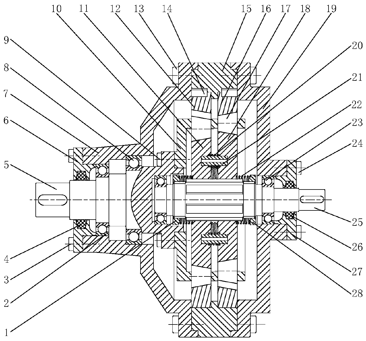
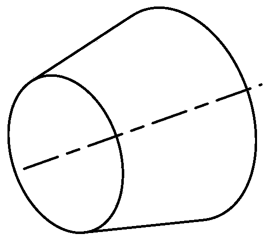
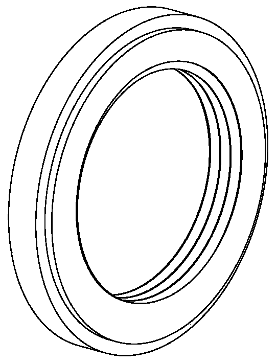
The invention discloses a double-shock-wave roller column movable tooth speed reducer with a gap eliminating mechanism. The double-shock-wave roller column movable tooth speed reducer mainly comprisesa first eccentric circle shock wave device, a second eccentric circle shock wave device, conical roller column movable teeth, a first center wheel, a second center wheel, a movable teeth frame, a shell, an input shaft and an output shaft. The two rows of conical roller column movable teeth are symmetrically arranged in opposite directions. The first eccentric circle shock wave device and the second eccentric circle shock wave device are arranged in opposite directions with a 180-degree phase difference. The conical roller movable teeth are adopted, so that the bearing capacity of the speed reducer can be improved, and gaps can be eliminated by adjusting the axial position. The input shaft is connected with the first eccentric circle shock wave device and the second eccentric circle shockwave device through a spline structure. Threads are machined at the two ends of the spline section to be connected with round nuts. Spring devices are arranged on the inner sides and outer sides of the first eccentric circle shock wave device and second eccentric circle shock wave device at the same time. The shock wave devices are pushed by elastic force to axially move to realize the function ofgap elimination. The bearing capability and the centering performance of the shock wave device and a shaft are improved by a spline. The elastic force of a spring is controlled through threaded connection.

Description

technical field [0001] The invention relates to a roller movable tooth reducer, in particular to a double-shock wave roller movable tooth reducer with an anti-backlash mechanism. Background technique [0002] Roller movable tooth transmission is the simplest structural form in movable tooth transmission, because of its simple structure and good transmission performance, it has attracted widespread attention. In the existing roller movable tooth transmission device, the movable tooth generally adopts cylindrical rollers, and steel balls are also used in some cases. After the device runs for a period of time, the movable tooth will wear out, the transmission device will have wear gaps, and the transmission noise will become larger. work has a greater impact. [0003] The patent application number is CN201310606488.8. A gapless power output device is installed between the body and the fixed wheel to generate a constant axial force to push the fixed wheel to move axially, and t...

Claims


Application Information

Patent Timeline
IPC IPC(8): F16H49/00F16H57/12F16H57/021F16H57/029
CPCF16H49/001F16H57/0006F16H57/021F16H57/029F16H2057/127
Inventor 宜亚丽郭争辉张爽金贺荣
Owner BEIJING XINGHANG MECHANICAL ELECTRICAL EQUIP
Why Eureka
Eureka Blog
Learn More