Display panel

A display panel, the same technology, applied in optics, instrumentation, electrical digital data processing, etc., can solve problems such as differences in other areas, voltage differences in liquid crystal cells, abnormal potential of touch electrodes 5, etc., and achieve the effect of simple design

Active Publication Date: 2019-07-05
NANJING CEC PANDA FPD TECH CO LTD
View PDF7 Cites 7 Cited by
  • Summary
  • Abstract
  • Description
  • Claims
  • Application Information

AI Technical Summary

Problems solved by technology

[0007] However, when the touch electrode is disconnected near 104, the scan line that can pull up the potential of the touch electrode 5 to offset the pull-down of the current scan line to the potential of the touch electrode 5 is located in a non-local touch electrode, and cannot be formed. Offset, the potential of the touch electrode 5 is abnormal, which will eventually cause the voltage difference in the liquid crystal cell near the touch electrode disconnection 104 to be different from other areas, resulting in horizontal stripes near the touch electrode junction

Method used


Image

  • Display panel
  • Display panel
  • Display panel

Examples


Embodiment 1

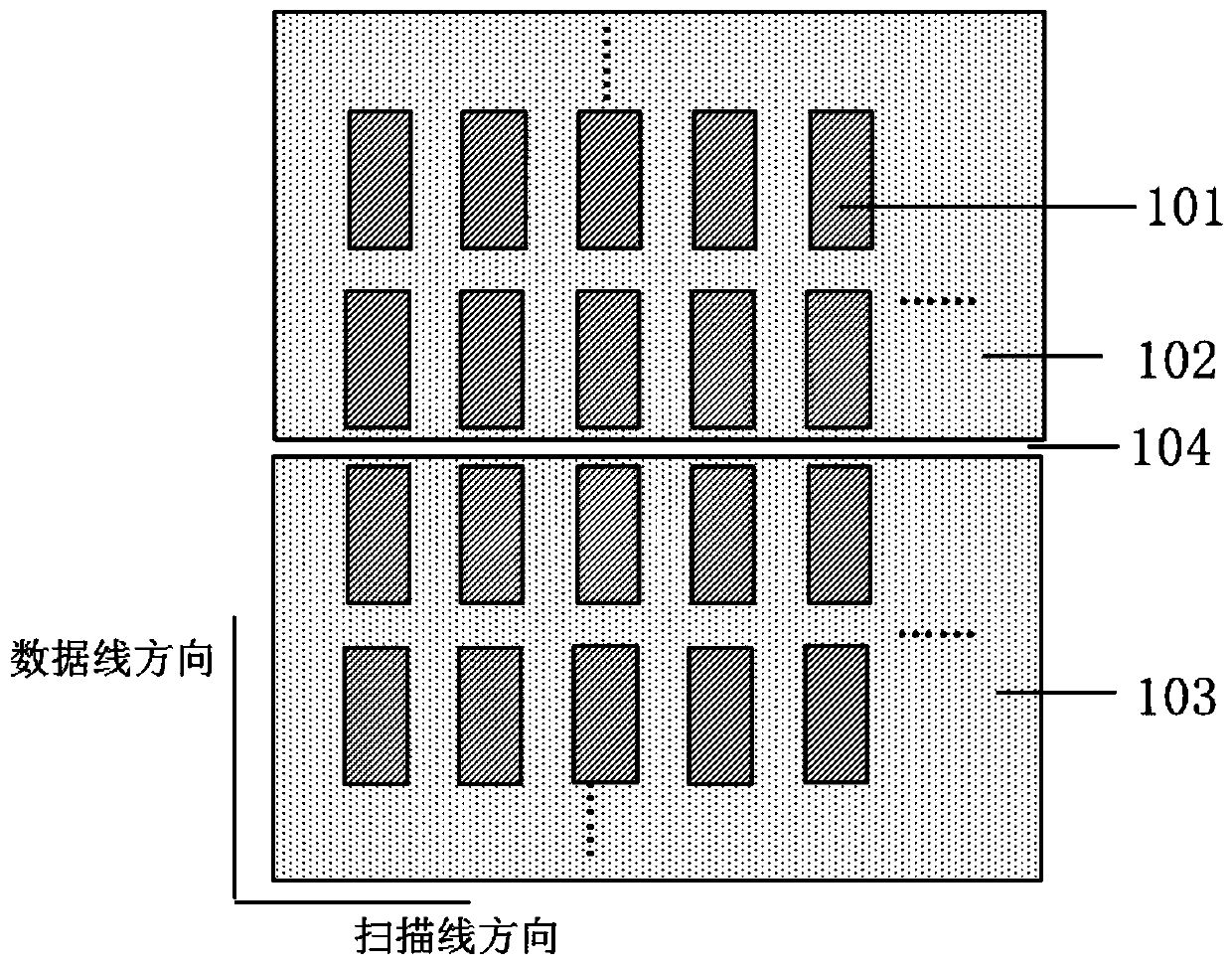
[0059] The display panel of this embodiment includes pixel units 101 in the 1st, 2nd, ..., n-2, n-1, n, n+1, ..., m-1, m rows from top to bottom in the column direction , and include the 1st, 2nd, ..., n-2, n-1, n, n+1, ..., m-1, m scan lines corresponding to each row of pixel units 101, wherein m>n +1, and n, m are both positive integers.

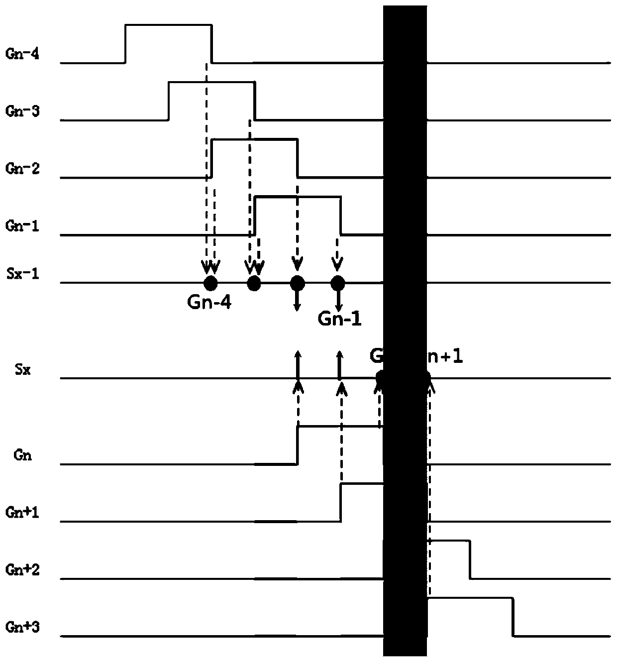
[0060] Such as Figure 4 As shown, the n−1th row of pixel units is the last row of first pixel units in the first touch electrode block 102 , and the nth row of pixel units is the first row of second pixel units in the second touch electrode block 103 . The scan line of the n-1 row inputs the n-1 scan signal Gn-1 into the n-1 row pixel unit, and the n-2 scan line inputs the n-2 scan signal Gn-2 into the n-2 For the row of pixel units, scanning signals such as Gn-3 and Gn-4 are sequentially input to the above row of pixel units. The scanning line of the nth row inputs the scanning signal Gn of the nth level into the pixel unit of the nth...


PUM


Abstract

The invention discloses a display panel and belongs to the field of display technologies. The display panel comprises a touch electrode, scanning lines, data lines, a plurality of pixel units, and a plurality of compensation signal groups; the scanning lines and data lines are arranged in a crossing manner; the plurality of pixel units are defined by means of the intersection of the scanning linesand the data lines; the touch electrode is segmented into a plurality of independent touch electrode blocks; the compensation signal line groups are corresponding to the disconnection portions of thetouch electrode respectively; parasitic capacitance is formed between the compensation signal line groups and the touch electrode so as to compensate voltage deviation on the touch electrode blocks caused by the jumping of the scanning signals, and therefore, horizontal stripes near the border of the touch electrode can be avoided.

Description

technical field [0001] The invention belongs to the field of display technology, and in particular relates to a display panel. [0002] technical background [0003] The structure of a conventional self-contained in-cell touch display panel is as follows: figure 1 shown. The touch electrode 5 is divided into several independent touch electrode blocks, each touch electrode block corresponds to a plurality of pixel units, each touch electrode block is connected to the touch signal transmission line through the touch electrode connection hole 6 4. The touch signal transmission line 4 is connected to the IC. When in the display stage, the touch signal transmission line 4 inputs the common electrode signal, the touch electrode 5 is used as a common electrode, and an electric field is formed between the touch electrode 5 and the pixel unit 8 to drive the liquid crystal display. When in the touch stage, the touch signal transmission line 4 inputs the touch sensing signal, and the...

Claims


Application Information

Patent Timeline
Patent Type & Authority Applications(China)
IPC IPC(8): G02F1/1333G02F1/1343G02F1/1362G02F1/1368G06F3/044
CPCG02F1/13338G02F1/134309G02F1/136286G02F1/1368G06F3/044G02F1/13606
Inventor 黄威
Owner NANJING CEC PANDA FPD TECH CO LTD
Why Eureka
Try Eureka