A kind of roller coating coating equipment and coating process

A coating process and equipment installation technology, which can be applied to devices for coating liquids on surfaces, coatings, pretreatment surfaces, etc. Viscosity and other issues to achieve the effect of ensuring quality and quality stability, improving accuracy and consistency, and good surface leveling

Active Publication Date: 2019-04-30
FUJIAN GANG HONG METAL TECH CO LTD
View PDF8 Cites 0 Cited by
  • Summary
  • Abstract
  • Description
  • Claims
  • Application Information

AI Technical Summary

Problems solved by technology

Less attention is paid to the coating construction of water-based coatings. For example, CN102009036B is only aimed at the fiberboard coating process. The coating roller is generally a rubber rubber roller or a silicone roller, which does not have sufficient surface viscosity and cannot ensure that the rubber roller is in the coating process. It has good material transfer and material placement performance, but cannot guarantee high-quality coating
The hardness index is generally HSA45-55. If it is too hard, it cannot be coated evenly and streaks are easy to appear; the diameter of the coating roller currently in use is relatively large, above 300mm, so the speed of the coating roller should not be too fast. In order to ensure the effect, the coating The rolling speed of the cloth roller is 1.1 to 1.2 times the line speed, otherwise the thickness of the coating will be too high and the paint will be wasted. During the curing process, solvent vapor is evaporated, and the vapor is mainly toluene and xylene, which cannot meet the requirements of environmental protection
[0005] The current production efficiency of stainless steel coating is generally at a low efficiency, and the curing process generally takes more than 5 minutes, and the relatively backward hot air curing technology is adopted, so the production efficiency and energy utilization rate are low

Method used


Image

  • A kind of roller coating coating equipment and coating process
  • A kind of roller coating coating equipment and coating process
  • A kind of roller coating coating equipment and coating process

Examples


Embodiment

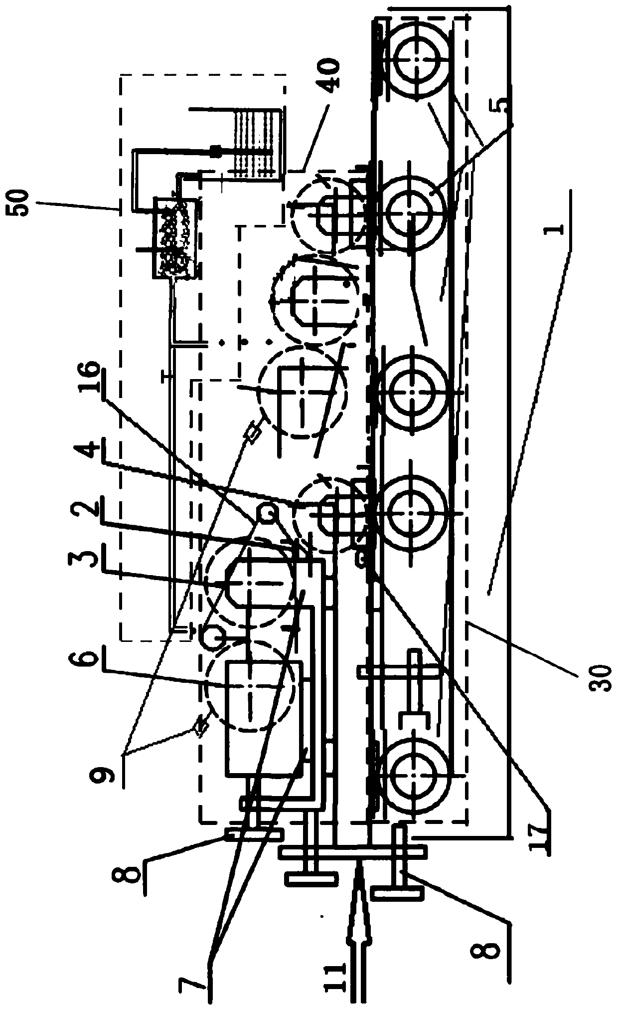
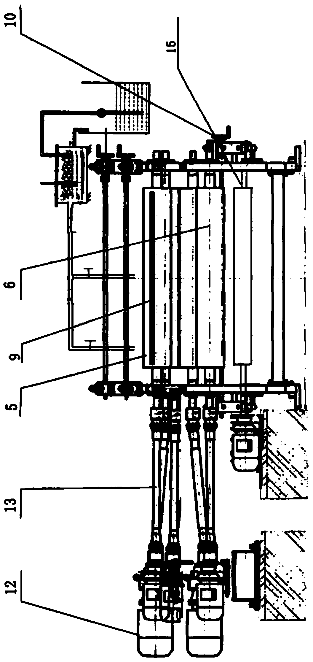
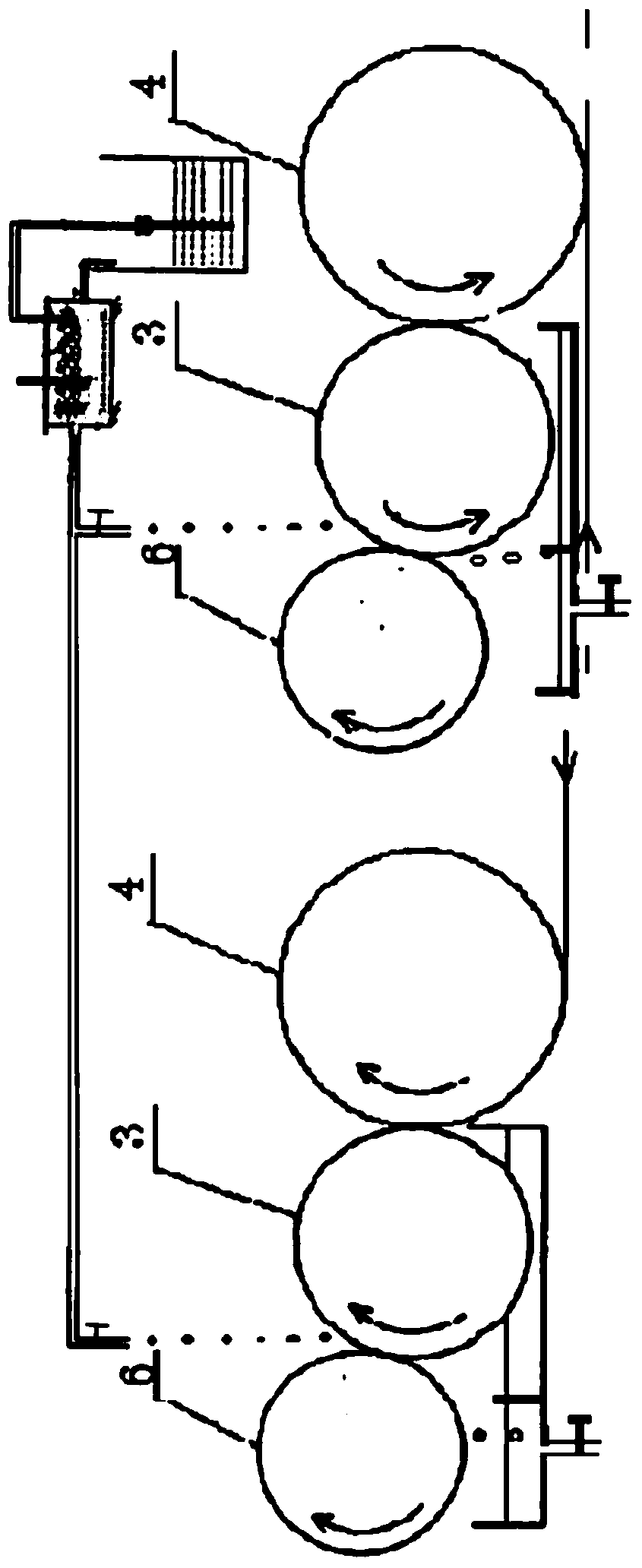
[0039] According to attached Figure 1-4 The roller coating equipment comprises a base (1), a drive system (30) connected to the base (1), a three-roller bottom reclaiming or upper feeding system (40) and a defoaming feeding system (50), The transmission system (30) is connected with the three-roller bottom reclaiming or upper feeding system (40), and the defoaming feeding system (50) extends into the three-roller lower reclaiming or upper feeding system through the feed port (22). above the metering roller (6) in the material system (40); it is characterized in that the three-roller bottom reclaiming or upper feeding system (40) consists of metering roller 1 (6), reclaiming roller 1 (3) and coating Cloth roll 1 (4); metering roll 2 (6), take-up roll 2 (3) and coating roll 2 (4); where metering roll 1 (6) and take-off roll 1 (3) are located on the sliding In the material basin (2) on the block guide rail (7), the slider guide rail (7) is connected on the base (1); the meterin...


PUM


Abstract

The invention discloses a roll coating device and a coating technology. The roll coating device comprises a base, and a driving system (30), a three-roll down-taking or up-feeding system (40) and a defoaming feeding system (50) which are sequentially connected, wherein the three-roll down-taking or up-feeding system (40) comprises sequentially arranged two sets of metering rolls (6), two sets of material taking rolls (3) and two sets of coating rolls (4); sliding block guide rails (7) are connected on the base (1); the metering roll 1 (6) is driven by a driving motor (12); and sharp knives (9) are connected on the metering rolls (6). The coating technology carried out through adopting the roll coating device is simple in operation and high in automation degree, the poor coating is easy and convenient to treat, and a coated product is high in adhesive force, can meet the bending requirement of stainless steel OT, can resist 5% acid alkali for 24 hours without change, can resist salt mist for 240 hours, and reaches the eight-grade standard; and compared with an oil coating, the coating adopted by the invention is non-combustible, unexplosive, VOC emission-free, non-toxic, harmless, safe and environment, and meets the national environmental protection policy and laws and regulations.

Description

technical field [0001] The invention relates to the coating field, in particular to a roller coating equipment and a coating process. Background technique [0002] At present, there are many advantages of mechanical coating: improving quality, improving efficiency, reducing occupied site area, reducing personnel operation, reducing energy consumption, protecting personnel's health and avoiding environmental pollution. [0003] In the field of painting and coating technology, most of the coatings in the existing coating machines are pumped into the material tank by air pump or diaphragm pump or directly supplied between the coating roller and the control roller, and will be produced in the material tank or coating roller. Bringing in a large number of tiny bubbles cannot be eliminated quickly. Because the surface tension of bubbles is different from that of no bubbles, it will lead to uneven thickness of the coating or bubble marks, forming fish eyes or uneven and smooth coat...

Claims


Application Information

Patent Timeline
Patent Type & Authority Patents(China)
IPC IPC(8): B05C1/12B05C13/02B05C11/10B05D7/14B05D3/12
CPCB05C1/12B05C11/10B05C13/02B05D3/12B05D7/14
Inventor 马文瑞林波吴子豹
Owner FUJIAN GANG HONG METAL TECH CO LTD
Why Eureka
Try Eureka