Device for exerting force on a roll of a fiber web processing machine

An application device, fiber web technology, applied in the field of applying force on components of fiber web processing machines, to achieve the effect of preventing downtime, saving costs and avoiding the problem of cross stripes

Active Publication Date: 2016-02-10
VALMET TECH OY
View PDF5 Cites 0 Cited by
  • Summary
  • Abstract
  • Description
  • Claims
  • Application Information

AI Technical Summary

Problems solved by technology

[0006] Utilize known device and method to be difficult to solve above-mentioned " cross-stripe " problem
[0007] Another problem arises from the friction of the seals mounted on the pistons against the cylinder housing the pistons, which can cause problems in precisely adjusting the force applied to the rollers

Method used


Image

  • Device for exerting force on a roll of a fiber web processing machine
  • Device for exerting force on a roll of a fiber web processing machine
  • Device for exerting force on a roll of a fiber web processing machine

Examples


Embodiment Construction

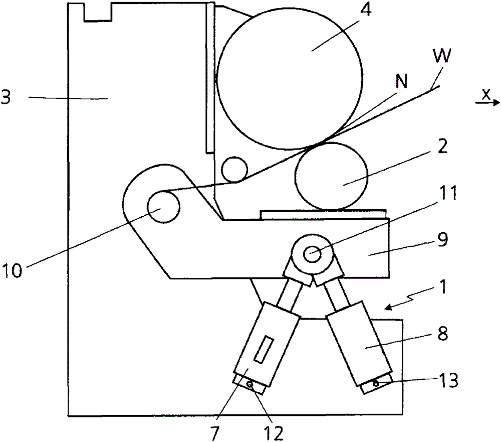
[0023] figure 1 A device 1 for exerting a force on a component of a fiber web processing machine, not shown in its entirety, which is configured as a roll 2 in this embodiment, is shown. The fibrous web processing machine may for example be a paper, board or tissue machine with which the fibrous web W is produced. In this embodiment, the roll 2 is part of a processing plant of a fiber web processing machine configured as a calender 3 . In addition to the calender 3, the treatment equipment can also be a drying section, a coating station, a dewatering unit or other similar treatment equipment. In addition to the roll 2 the calender 3 also has a further roll 4 , but further rolls can also be present in the calender 3 . In particular, the calender 3 can be designed as a multi-roll calender, it being immaterial at what angle the individual rolls are arranged relative to one another.

[0024] Between the two rolls 2 and 4 of the calender 3 a roll nip N is formed, through which t...


PUM


Abstract

The apparatus (1) has two independently controllable force applications units (7,8) provided at end regions of the component (2), so that different high forces are applied to the component. The force application units are mounted at processing device (3) of fibrous web processing machine in the running direction of the fibrous web (W) in movable state. An independent claim is included for method for applying force to component of fibrous web processing machine.

Description

technical field [0001] The invention relates to a device for exerting a force on a component of a fiber web processing machine. Furthermore, the invention also relates to a method of exerting a force on a component of a fiber web processing machine. Background technique [0002] A device of this type and a corresponding method are known from DE 112005002147 A1. A similar device is also described in patent document US4332192. [0003] In fiber web processing machines, for example for the manufacture and / or processing of paper, board or tissue paper or textiles, the fiber web is subjected in different process steps (for example drying or calendering) between two rolls forming a roll nip extrusion. Therefore, in most cases one of the rollers is arranged to be movable, while the other roller is fixedly mounted. With the aid of devices of this type, forces can be exerted on the movable rolls in order to vary the pressing force in the roll gap, the so-called roll gap pressure ...

Claims


Application Information

Patent Timeline
Patent Type & Authority Patents(China)
IPC IPC(8): B65H23/34
CPCD21G1/004
Inventor 汤米·万哈拉阿马斯·格特
Owner VALMET TECH OY
Why Eureka
Try Eureka