
Insulating sleeve and manufacturing method thereof

A technology for insulating sleeves and manufacturing methods, which is applied in the field of insulating sleeves and its manufacturing, and can solve problems such as increasing process difficulty, reducing product yield, increasing product size, etc., and achieves reducing process difficulty, reducing product size, and improving electric field strength. evenly distributed effect

Inactive Publication Date: 2019-07-05
JIANGSU SHENMA ELECTRIC CO LTD
View PDF4 Cites 1 Cited by
  • Summary
  • Abstract
  • Description
  • Claims
  • Application Information

AI Technical Summary

Problems solved by technology

However, installing the metal shielding electrode in the insulating sleeve will increase the product size, and if the metal shielding electrode is not installed correctly during the installation process, it may lead to a decrease in the electrical strength of the insulating sleeve, resulting in a lower product yield
Therefore, by installing a metal shielding electrode at the bottom of the insulating sleeve to solve the problem of electric field concentration at the sharp corner of the adhesive groove, it will not only increase the size of the product, but also increase the difficulty of the process

Method used


Image

  • Insulating sleeve and manufacturing method thereof
  • Insulating sleeve and manufacturing method thereof
  • Insulating sleeve and manufacturing method thereof

Examples


Embodiment Construction

[0023] The technical solutions in the embodiments of the present application are clearly and completely described below in conjunction with the accompanying drawings in the embodiments of the present application. Obviously, the described embodiments are only some of the embodiments of the present application, not all of them. Based on the embodiments in this application, all other embodiments obtained by persons of ordinary skill in the art without making creative efforts belong to the scope of protection of this application.

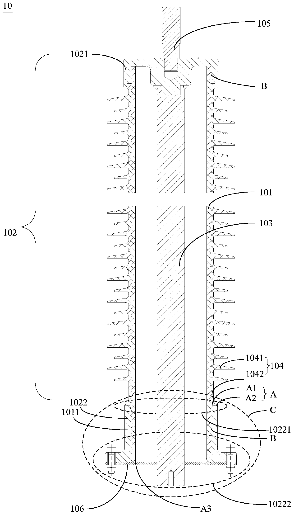
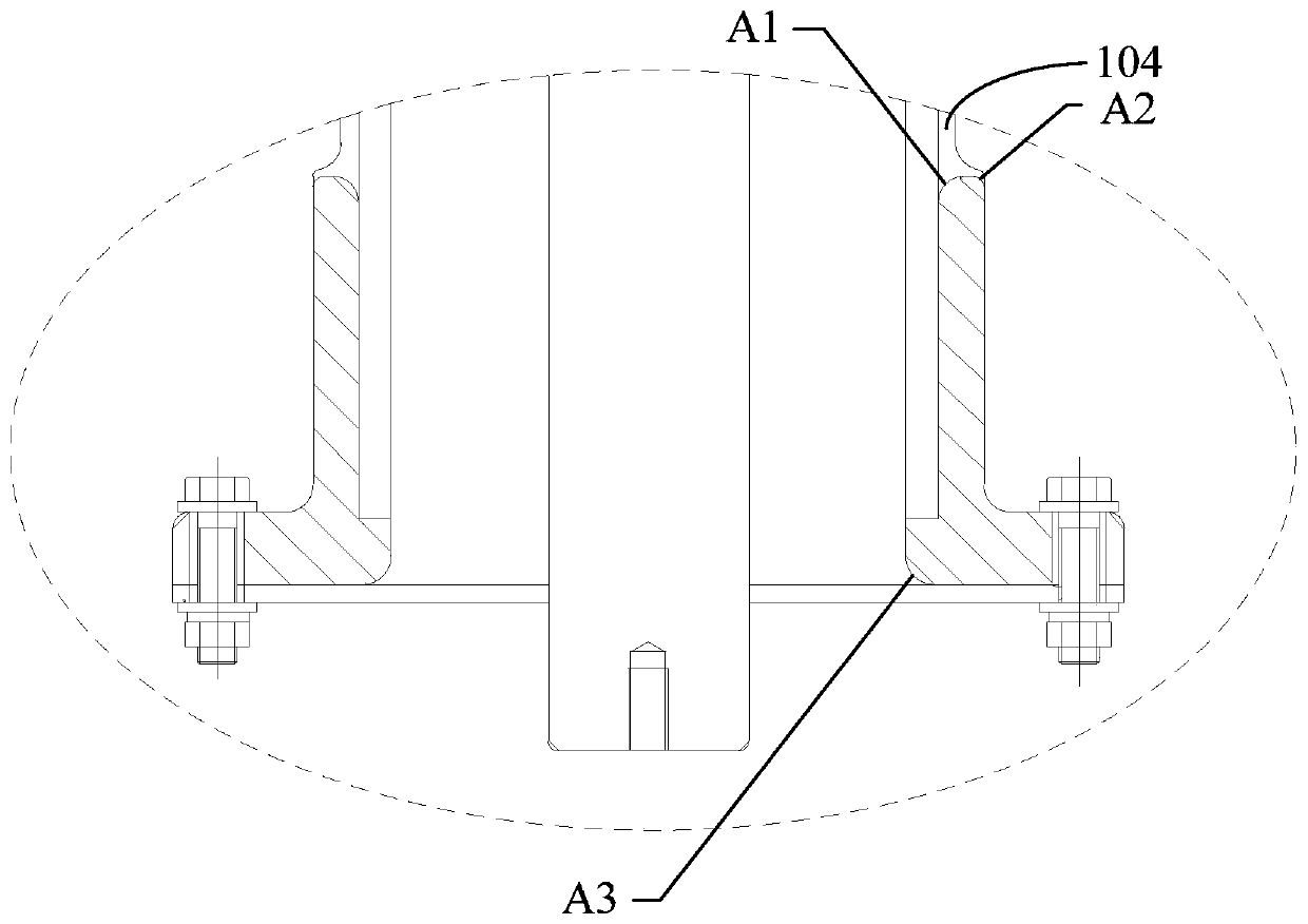
[0024] see figure 1 , figure 1 It is a structural schematic diagram of an embodiment of the insulating sleeve 10 of the present application. The insulating bushing 10 includes an insulating tube 101 , two flanges 102 and a conductive rod 103 . The two flanges 102 include a high-voltage end flange 1021 and a low-voltage end flange 1022 , which are fixedly sleeved on both ends of the insulating tube 101 . In an implementation scenario, the insulating pi...


PUM

PropertyMeasurementUnit
thicknessaaaaaaaaaa
radiusaaaaaaaaaa

Abstract

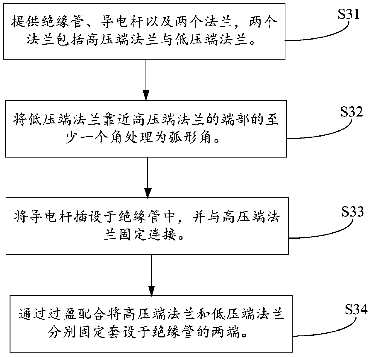
The invention discloses an insulating sleeve and a manufacturing method thereof. The insulating sleeve comprises an insulating tube, two flanges and a conducting rod, wherein the two flanges comprisea high-voltage end flange and a low-voltage end flange which respectively fixedly sleeve the two ends of the insulating tube; and the conducting rod is fixedly connected with the high-voltage end flange and is inserted into the insulating tube; and at least one angle, close to the end portion of the high-voltage end flange, of the low-voltage end flange is an arc angle. In this way, the low-voltage end flange is uniform in distribution of the intensity of an electric field with no need for arrangement of a metal shielding electrode to simplify the structure of the insulating sleeve, reduce thesize of the product and reduce the process difficulty.

Description

technical field [0001] The present application relates to the technical field of electric equipment, in particular to an insulating sleeve and a manufacturing method thereof. Background technique [0002] Insulating bushings are important components in power systems. At present, the flange and the insulating tube in the insulating bushing are usually fixed by a glue-fitting process. Specifically, multiple adhesive grooves are generally opened on the inner wall of the flange and the outer wall of the insulating tube, and epoxy resin glue is injected into the grooves through the glue injection hole of the flange, and then it can be cured at high temperature. However, in actual engineering, the low-voltage end flange is generally grounded to maintain zero potential. Therefore, the electric field intensity at the sharp corner of the adhesive groove inside the low-voltage end flange is very high, and the field intensity distribution is uneven. [0003] In view of this, in the ...

Claims


Application Information

Patent Timeline
Patent Type & Authority Applications(China)
IPC IPC(8): H01B17/58H01B17/60H01B17/64H01B19/00
CPCH01B17/583H01B17/60H01B17/64H01B19/00
Inventor 马斌孟广泽庄奥运刘俊黄从鹏
Owner JIANGSU SHENMA ELECTRIC CO LTD
Learn More