Underground cable laying device

An underground cable, a pair of technology, applied in the direction of cable laying equipment, etc., can solve the problem that the automatic stop of the pay-off pulley cannot be realized, and the protection of the underground cable is difficult.

Active Publication Date: 2019-07-05
国网河南省电力公司社旗县供电公司
View PDF7 Cites 6 Cited by
  • Summary
  • Abstract
  • Description
  • Claims
  • Application Information

AI Technical Summary

Problems solved by technology

However, this invention cannot realize the automatic stop of the pay-off bloc...

Method used


Image

  • Underground cable laying device
  • Underground cable laying device
  • Underground cable laying device

Examples


Embodiment 1

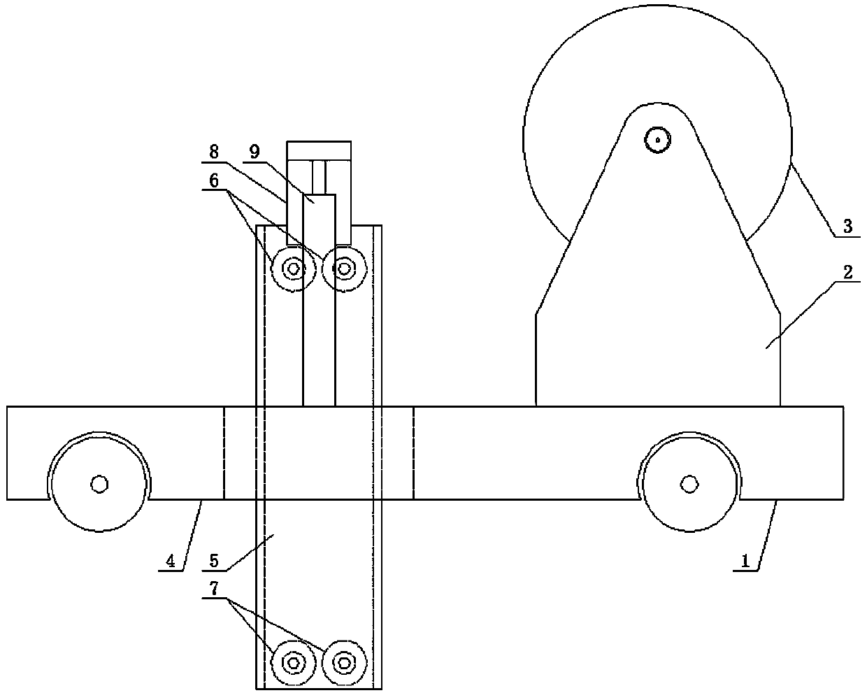
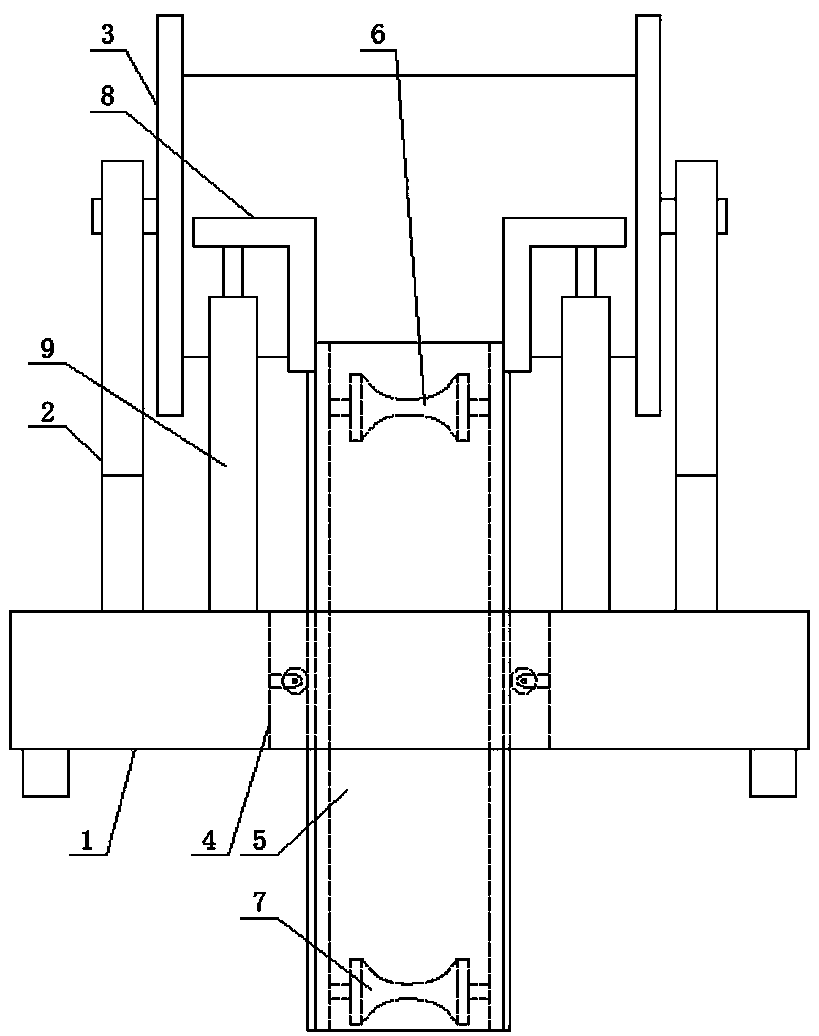
[0032] Such as figure 1 and figure 2 As shown, an underground cable laying device includes a trailer body 1, a pay-off frame 2 is arranged on the front side of the upper part of the trailer body 1, a cable reel 3 is rotatably arranged on the pay-off frame 2, and a cable reel 3 is arranged on the upper part of the trailer body 1. The rear side is provided with a guiding mechanism for guiding the wire into the cable shaft;

[0033] The guide mechanism includes a rectangular through hole 4 arranged on the rear side of the upper part of the trailer body 1, a rectangular cylinder 5 is arranged in a lifting manner in the rectangular through hole 4, and the inner side of the upper opening of the rectangular cylinder 5 is rotated. A pair of upper thread rolling wheels 6, a pair of lower thread rolling wheels 7 are rotated inside the lower opening of the rectangular cylinder 5, and a pair of inverted L-shaped push plates 8 are symmetrically arranged on the left and right sides of the...

Embodiment 2

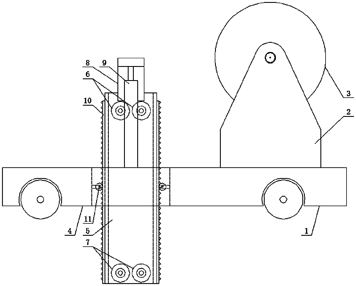
[0037] Such as image 3 As shown, the difference between it and Embodiment 1 is that a tooth rack 10 is respectively arranged vertically on the four surfaces of the rectangular cylinder 5, and a corresponding rack 10 is arranged on the four inner walls of the rectangular via hole 4 respectively. A pinion 11 with a guide function that matches the rack 10.

[0038] In this embodiment, in order to prevent the rectangular cylinder from inclining when the device is used to lay cables in the underground cable shaft, a rack is arranged vertically on the four sides of the rectangular cylinder, and a rack is installed on the four sides of the rectangular via hole. A pinion gear with a certain guiding function is arranged on the four inner walls respectively and cooperates with the corresponding rack.

Embodiment 3

[0040] Such as Figure 4 Shown, its difference with embodiment 2 is:

[0041] The upper part of the trailer body 1 and the front and rear sides of the rectangular cylinder 5 are respectively provided with a locking mechanism for locking. The locking mechanism includes a slide rail 12 arranged on the upper part of the trailer body 1. A slide block 13 is slidably arranged on the slide rail 12, and the front end of the slide block 13 has a shape tooth 14 matched with the corresponding rack 10. A second automatic telescopic rod 16 is horizontally arranged on the inner surface of the inner surface, and the free end of the second automatic telescopic rod 16 is arranged on the slider 13 .

[0042] The second automatic telescopic rod 16 is an electric telescopic rod.

[0043] In this embodiment, in order to prevent the rectangular cylinder of the guiding mechanism from moving up and down when the device is used to lay cables in the underground cable shaft, one is provided on the upp...


PUM


Abstract

The invention discloses an underground cable laying device. The underground cable laying device comprises a trailer body, wherein a pay-off rack is arranged on the front side of the upper part of thetrailer body, and the rear side of the upper part of the trailer body is provided with a guide mechanism for guiding the paying-off in a cable well; the guide mechanism comprises a rectangular via hole which is formed in the rear side of the upper part of the trailer body; a rectangular barrel is arranged in the rectangular via hole in a lifting mode; a pair of upper rolling wheels are rotationally arranged on the inner side of the upper opening of the rectangular barrel, a pair of lower rolling wheels are arranged on the inner side of the opening in the lower portion of the rectangular barrelin a rotating mode; a pair of inverted L-shaped push plates are symmetrically arranged on the left side and the right side of the upper end of the rectangular barrel; and a first automatic telescopicrod is arranged on the trailer body and located below the inverted L-shaped push plates in the vertical direction; the situation that the cable insulation layer is damaged due to the fact that the cable is not guided when the cable is laid in the underground cable well can be effectively solved, the extending depth of the guide mechanism can be adjusted according to the depth of the cable well, so that it is ensured that the cable cannot be directly rubbed with the lower edge of the cable well after entering the cable tunnel.

Description

technical field [0001] The invention relates to the technical field of power cable laying equipment, in particular to an underground cable laying device. Background technique [0002] Underground cables refer to cables that are often buried underground compared with common overhead lines, so they are also called underground cables. A cable is a wire made of one or more mutually insulated conductors surrounded by an insulation and a protective layer, and is used to transfer power or information from one place to another. After entering the modern society, due to the shortage of urban land, high traffic pressure, city appearance construction and other reasons, large cities generally adopt underground cable transmission methods, especially the use of laying cable lines in pipes or trenches, and setting up pipes or trenches on the ground. Connected to the cable shaft for maintenance. Compared with overhead lines, cables have the advantages of small footprint, reliable power tr...

Claims


Application Information

Patent Timeline
IPC IPC(8): H02G1/06
CPCH02G1/06
Inventor 石岩张性东邱国林王伟焦玉振雷震姜红军惠东军张春王丽王志纯张菲张浩
Owner 国网河南省电力公司社旗县供电公司
Why Eureka
Try Eureka