
Coil rail type linear motor

A technology of linear motors and coils, applied in the field of electric motors, can solve problems such as short thrust maintenance time, damaged stator rails, burnt and short-circuited mover wire tubes, etc., to eliminate contact resistance and friction resistance, prolong service life, and eliminate power supply rails Effect

Pending Publication Date: 2019-07-05
郑雨
View PDF0 Cites 0 Cited by
  • Summary
  • Abstract
  • Description
  • Claims
  • Application Information

AI Technical Summary

Problems solved by technology

[0002] Linear motor is a type of motor classified according to the power output mode. Similar to traditional rotary motors, linear motors can also be divided into brushed and brushless. During the operation of brushed linear motors, the mover needs to make surface contact with the stator. Electricity transmission can generate ampere force in the magnetic field and move by force, and this contact type transmission has a certain contact resistance, and when the stator moves, the contact resistance increases and generates a lot of Joule heat, which will accumulate in a large amount on the mover The contact between the armature and the stator rail will cause huge damage to the stator rail, so the life of the magnetic rail linear motor will be very low, and because the electric conversion efficiency of the single current wire is magnetic, the magnetic rail linear motor will waste a lot of energy. electric energy
[0003] In order to solve the problem of the life of the magnetic rail linear motor, people invented the induction linear motor. There is no contact between the stator and the mover in this type of linear motor. The changing magnetic field generated by the coil generates an induction circuit. At the same time, the direction of the induced current in the mover coil is the same as that of the stator coil, which will generate a Lenz force that pushes the mover coil. The whole process only needs to supply power to the stator coil. The mover coil only needs to be placed in a certain position to generate thrust for the mover coil. Although this type of linear motor has achieved an increase in life, the maintenance time of the thrust is very short due to its structural characteristics, and it is difficult for the stator coil and the mover coil. There are strict requirements on the parameters and shape, and in order to maintain the unidirectional Lenz force, the power supply to the stator coil must adopt pulsed direct current with a specific waveform. If it is only a single acceleration, there is no limit to the power of the pulsed power. To obtain a greater speed of the coil, multi-stage stator coils are often used to accelerate the mover coil multiple times. At this time, the power of the pulse power needs to be limited, otherwise the mover wire tube will be burned and short-circuited due to the Joule heat of the induced current. , which in turn reduces the practicality of existing linear motors

Method used


Image

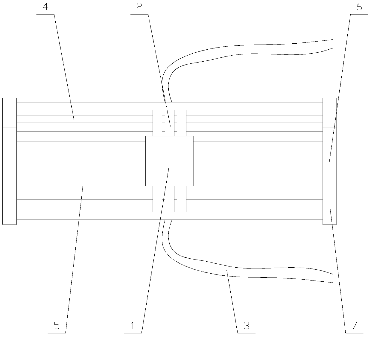
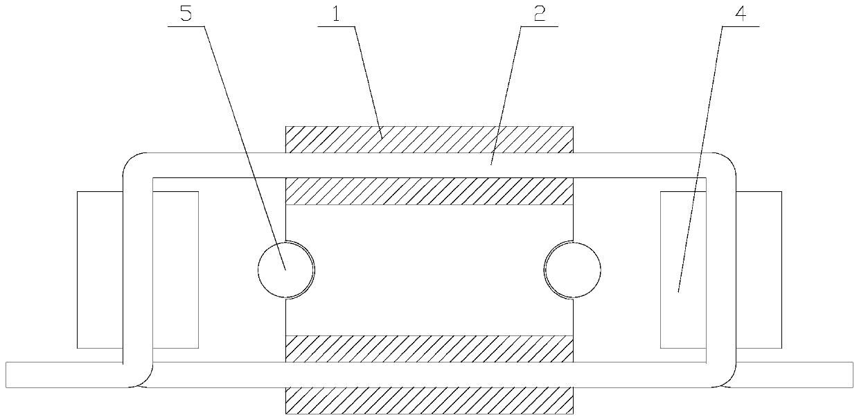
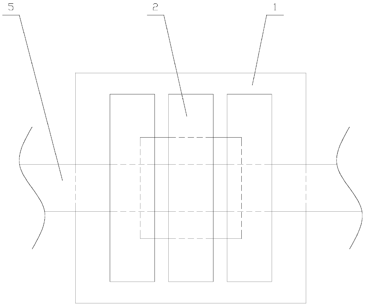
  • Coil rail type linear motor
  • Coil rail type linear motor
  • Coil rail type linear motor

Examples


Embodiment Construction

[0018] The present invention is described in further detail now in conjunction with accompanying drawing. These drawings are all simplified schematic diagrams, which only illustrate the basic structure of the present invention in a schematic manner, so they only show the configurations related to the present invention.

[0019] like Figure 1-3 As shown, a ring-rail linear motor includes a slider 1, a coil 2, a magnetic field device, two fixed end blocks and two wires 3, the two fixed end blocks are arranged in parallel, and the slider 1 and the magnetic field device are located at Between the two fixed end blocks, the slider 1 is parallel to the fixed end block, the shape of the section perpendicular to the fixed end block of the slider 1 is round, and the coil 2 is parallel to the fixed end block. The shape of the cross section of the coil 2 is circular, the upper and lower sides of the coil 2 pass through the upper and lower sides of the slider 1 respectively, and the two ...


PUM


Abstract

The invention relates to a coil rail type linear motor comprising a sliding block, a coil, a magnetic field device, two fixed end blocks and two wires; the magnetic field device comprises two magneticfield components, the magnetic field component comprises two permanent magnets, the fixed end block comprises a fixed plate and two side plates, and the coil rail type linear motor supplies power tothe coil through a wire made of the flexible strip-shaped electric wire, thereby eliminating contact resistance and friction resistance, and eliminating a power supply rail, so that the electrified coil is subjected to ampere force of a constant magnetic field generated by a permanent magnet so as to drive the sliding block to move between the two fixed end blocks, thereby avoiding joule heat frombeing generated during movement of the sliding block, prolonging the service life of the device, and further improving the practicability of the coil rail type linear motor.

Description

technical field [0001] The invention relates to the field of motors, in particular to a ring-rail linear motor. Background technique [0002] Linear motor is a type of motor classified according to the power output mode. Similar to traditional rotary motors, linear motors can also be divided into brushed and brushless. During the operation of brushed linear motors, the mover needs to make surface contact with the stator. Electricity transmission can generate ampere force in the magnetic field and move by force, and this contact type transmission has a certain contact resistance, and when the stator moves, the contact resistance increases and generates a lot of Joule heat, which will accumulate in a large amount on the mover The contact between the armature and the stator rail will cause huge damage to the stator rail, so the life of the magnetic rail linear motor will be very low, and because the electric conversion efficiency of the single current wire is magnetic, the magn...

Claims


Application Information

Patent Timeline
Patent Type & Authority Applications(China)
IPC IPC(8): H02K41/03
CPCH02K41/031
Inventor 郑雨
Owner 郑雨
Learn More