Service sending and receiving method and device in optical transport network

A technology for optical transport network and service transmission, which is applied in the field of communication and can solve problems such as bandwidth waste

Active Publication Date: 2019-07-05
ZTE CORP
View PDF4 Cites 15 Cited by
  • Summary
  • Abstract
  • Description
  • Claims
  • Application Information

AI Technical Summary

Problems solved by technology

[0008] Embodiments of the present invention provide a service sending and receiving method and device in an optical transport network, to at least solve the problem in the related art that transmission of optical transport services by dividing the payload area into time slots results in serious bandwidth waste

Method used


Image

  • Service sending and receiving method and device in optical transport network
  • Service sending and receiving method and device in optical transport network
  • Service sending and receiving method and device in optical transport network

Examples


Embodiment 1

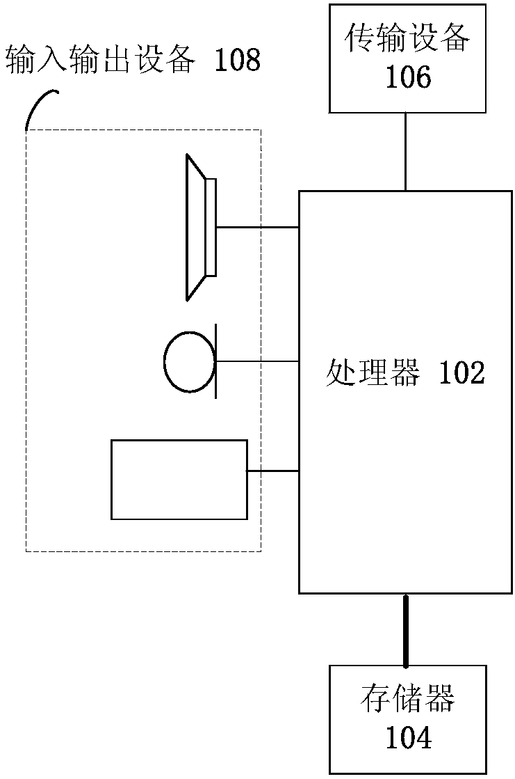
[0100] The method embodiment provided in Embodiment 1 of the present application may be executed in a mobile terminal, a computer terminal, or a similar computing device. Taking running on a mobile terminal as an example, image 3 It is a hardware structural block diagram of a mobile terminal of a service sending method in an optical transport network according to an embodiment of the present invention. Such as image 3 As shown, the mobile terminal 10 may include one or more ( image 3 Only one is shown in the figure) a processor 102 (the processor 102 may include but not limited to a processing device such as a microprocessor MCU or a programmable logic device FPGA) and a memory 104 for storing data. Optionally, the above-mentioned mobile terminal also A transmission device 106 for communication functions as well as input and output devices 108 may be included. Those of ordinary skill in the art can understand that, image 3 The shown structure is only for illustration, ...

Embodiment 2

[0144] According to another embodiment of the present invention, a service receiving method in an optical transport network is also provided, Figure 8 is a flowchart of a service receiving method in an optical transport network according to an embodiment of the present invention, such as Figure 8 As shown, the process includes the following steps:

[0145] Step S802, receiving an OTN interface frame of the optical transport network, wherein the payload area of ​​the OTN interface frame includes N cells of a fixed size, one cell carries one ODU service, and N is an integer greater than or equal to 1;

[0146] Step S804, demapping ODU services from the N cells in the payload area of ​​the OTN interface frame.

[0147] Through the above steps, since the ODU service is demapped from the N cells in the payload area of ​​the OTN interface frame, it is possible to solve the problem of transmitting optical transmission by dividing the payload area into time slots in the related art...

example 1

[0160]Two OTN devices transmit two Ethernet services with a bandwidth of 5GE through the OTU2, and the OTU2 payload area is divided by cells provided by the present invention instead of time slots.

[0161] Step 1, the size of the payload area of ​​OTU2 is 4*3808 bytes, and the cell size is set to 32 bytes, which can be divided into (4*3808) / 32=476 cells in total, and the bandwidth of each cell is OPU2 Payload bandwidth / 476, all cell numbers are 0, the first bit of each cell is cell type identification, and 0 means that all (32*8-1) bits in this cell are services , which is 1 means that (32*8-1) bits in this cell are all control information.

[0162] Step 2. At the sending end, map the two 5GE Ethernets to the corresponding two ODUflexes, and the bandwidth of each ODUflex is about 5G.

[0163] Step 3: Calculate the number of cells occupied by each ODUflex according to the ODUflex bandwidth and the cell bandwidth. In this example, 238 cells need to be allocated to each ODUflex...


PUM


Abstract

The invention provides a service sending and receiving method and device in an optical transport network. The service sending method in the optical transport network comprises the steps of mapping anoptical transmission data unit (ODU) service into cells of a payload area of an optical transport network (OTN) interface frame, wherein the payload area comprises N cells with the fixed size, one cell bears one ODU service, and N is an integer larger than or equal to 1; and packaging and sending the OTN interface frame. Through the method and the device, the problem of serious bandwidth waste caused by transmitting the optical transmission service by dividing the payload area into the time slots in the prior art is solved, and the effect of improving the bandwidth utilization rate of the optical transmission network is achieved.

Description

technical field [0001] The present invention relates to the field of communications, in particular to a method and device for sending and receiving services in an optical transport network. Background technique [0002] The Optical Transport Network (OTN) standard is formulated by the International Telecommunication Union (ITU-T) and is an important standard for optical transmission equipment. Now almost all long-distance transmission networks are composed of equipment based on the Optical Transport Network standard. . [0003] The OTN has its standard signal format, including Optical Transport Unit (OTUk for short) (k=1, 2, 3, 4), FlexO and new OTN signals defined in the future. Optical transport network signals are used to carry various non-OTN signals or multiple low-speed optical channel transmission unit (Optical Digital Unit, referred to as ODUi) (i=0,1,2,2e,3,4,flex) signals, and ODUi The rate is lower than the ODUk rate, and the low-speed ODUi (i<k) signal will ...

Claims


Application Information

Patent Timeline
Patent Type & Authority Applications(China)
IPC IPC(8): H04J3/16
CPCH04J3/1664H04J3/16H04J14/08H04J3/1652H04J2203/0071H04J2203/0091
Inventor 张源斌苑岩
Owner ZTE CORP
Why Eureka
Try Eureka