Laboratory centrifuge
A laboratory centrifuge and sensor technology, applied to centrifuges and other directions, can solve problems such as high adjustment costs, increased precession of gyroscopes, and reduced offsets
- Summary
- Abstract
- Description
- Claims
- Application Information
AI Technical Summary
Problems solved by technology
Method used
Image
Examples
Embodiment Construction
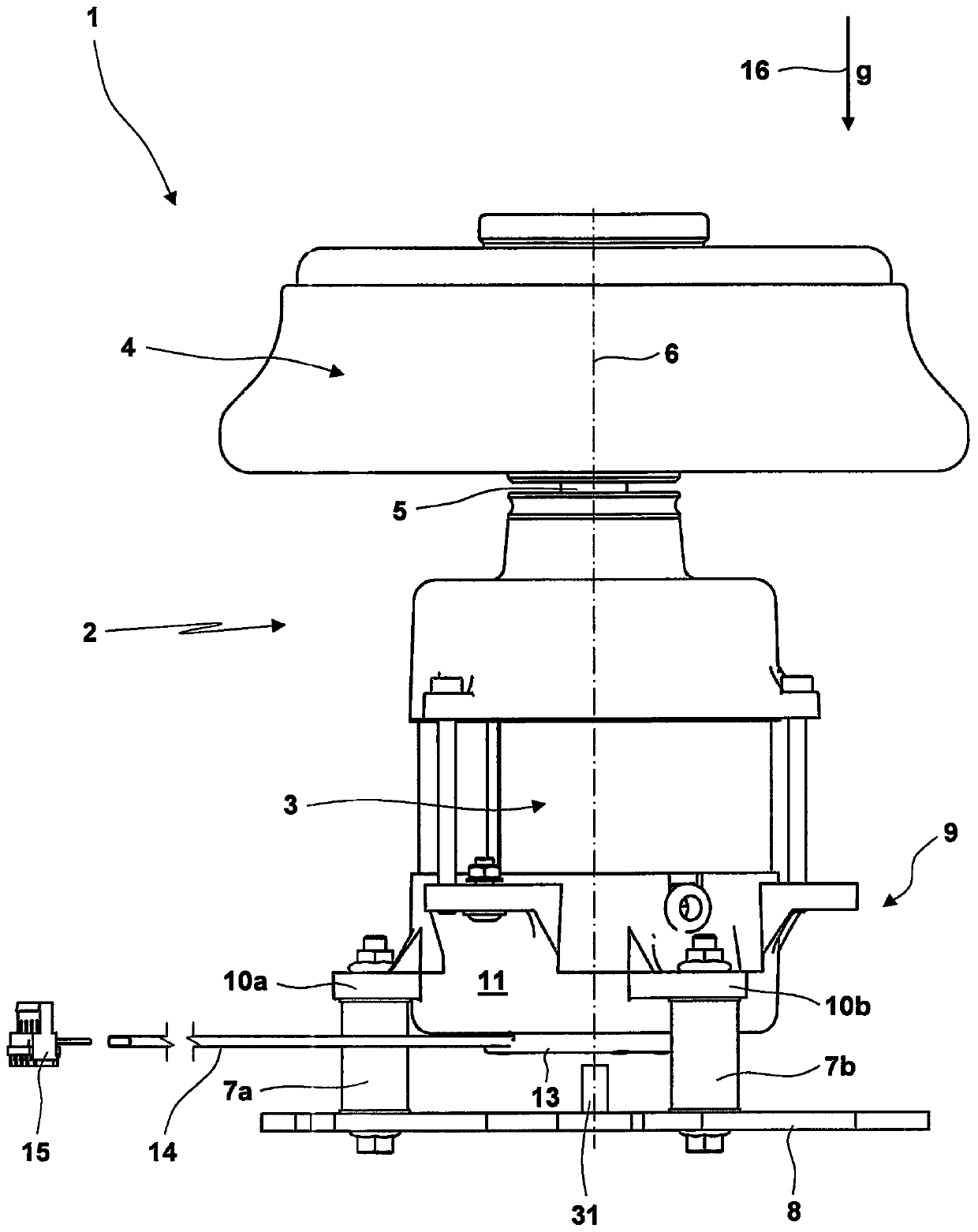
[0066] figure 1 The components of the laboratory centrifuge 1 are shown in a horizontal view. The centrifugal train 2 has a drive 3 , a rotor 4 and a drive and / or rotor shaft 5 via which the drive 3 can rotate the rotor 4 about a longitudinal axis and / or an axis of rotation 6 .
[0067] The centrifuge train 2 is supported in a resilient and damped manner on the housing 8 of the laboratory centrifuge 1 via spring and / or damping devices 7a, 7b. The centrifugal train 2 and the spring and / or damping device 7 form an oscillating system 9 . In the vibration system 9 , the centrifugal train 2 forms the vibration mass, while the stiffness and damping of the vibration system 9 are predetermined by the spring and / or damping device 7 . The spring and / or damping devices 7a, 7b preferably implement an offset and thus a degree of freedom of possible vibrations of the vibration system 9 as follows:
[0068] a) deflection and vibration in the direction of the longitudinal axis and / or the a...
PUM
 Abstract
Description
Claims
Application Information
 - R&D
- Intellectual Property
- Life Sciences
- Materials
- Tech Scout
- Unparalleled Data Quality
- Higher Quality Content
- 60% Fewer Hallucinations
Browse by: Latest US Patents, China's latest patents, Technical Efficacy Thesaurus, Application Domain, Technology Topic, Popular Technical Reports.
© 2025 PatSnap. All rights reserved.Legal|Privacy policy|Modern Slavery Act Transparency Statement|Sitemap|About US| Contact US: help@patsnap.com


