Bending equipment

A technology of equipment and bending arms, applied in heat exchange equipment, metal processing equipment, feeding devices, etc., can solve the problems of reducing product yield, easy damage of flat tubes, and straining the surface of heat exchangers, and reduce constraints. , The effect of improving the yield rate and reducing the probability of strain

Active Publication Date: 2019-07-09
浙江长兴和良智能装备有限公司
View PDF5 Cites 6 Cited by
  • Summary
  • Abstract
  • Description
  • Claims
  • Application Information

AI Technical Summary

Problems solved by technology

[0005] The applicant found the following problems in the process of bending the flat tube of the microchannel heat exchanger by using the above-mentioned bending equipment: (1) Due to the limited position of the clamping device on the bending arm, there is a strain on the tube. The problem on the surface of the heater leads to a low yield rate of the flat tube; (2) The flat tube at the clamping position on the upper and lower edges is easily damaged and the yield rate of the product is reduced; (3) The bend is found When the equipment bends microchannel heat exchangers of different sizes and models, it needs to replace the clamping device first to reduce the production efficiency of the equipment; (4) It is difficult to make the raised height of the flat tube after bending for the desired height

Method used


Image

  • Bending equipment
  • Bending equipment
  • Bending equipment

Examples


Embodiment

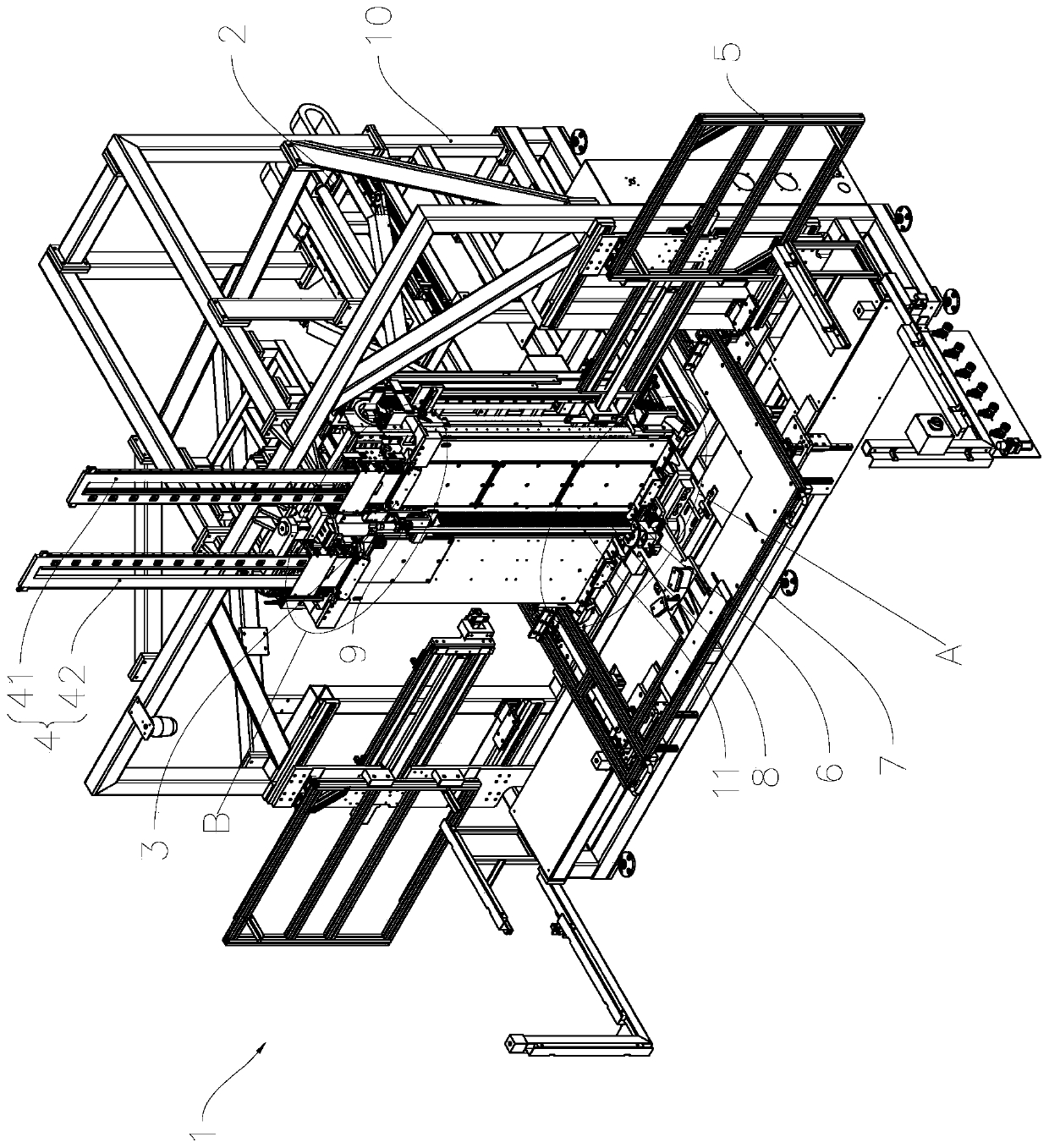
[0043] see figure 1 , the bending equipment 1 of the present invention includes a frame 10, a control unit and a bending unit 2 installed on the frame 10, a clamping unit 3, a centering unit 5, a mandrel unit 11, a pick unit 6, and a feeding unit 7. Plug unit 8 and pressing protrusion unit 9 .

[0044] The control unit is not shown in the drawings, and it includes a processor, a memory, and a control touch screen installed on the foundation or frame. The processor receives instructions input by the operator through the control touch screen, and executes the corresponding computer program in the memory according to the instructions. Each unit in the control bending equipment 1 cooperates to perform operations such as centering, inserting, picking, pulling out, and bending the workpiece.

[0045] see Figure 1 to Figure 4 , the bending unit 2 includes a bending servo motor 20, a bending screw 21, a driven nut, a bending slide 22, a left bending linear guide 231, a right bendin...


PUM


Abstract

The invention relates to bending equipment, and belongs to the technical field of bending machining. The bending equipment comprises a rack, a clamping unit, a core rod unit, a shifting unit and a bending unit, wherein the clamping unit, the core rod unit, the shifting unit and the bending unit are arranged on the rack, and the bending unit comprises a left bending arm and a right bending arm which are hinged through a bending rotating shaft; and the clamping unit comprises a transverse floating mounting frame which can be transversely arranged on one bending arm in a floating and sliding mode, and a clamping device which is arranged on the transverse floating mounting frame and is used for clamping a to-be-bent workpiece. The clamping unit is arranged to comprise the transverse floating mounting frame and the clamping device, so that the clamping device can freely move in the transverse direction in a floating mode relative to the correspondingly bending arm in the bending process, sothat restriction of a heat exchanger in the floating transverse direction can be reduced, the position change in the bending process can be better matched, so that the product yield can be improved,and the bending equipment can be widely applied to the field of manufacture of evaporators and the like.

Description

[0001] This application is a divisional application for an invention patent with the application number CN201710792636.8 and the invention name "a bending equipment". technical field [0002] The invention relates to bending processing equipment, in particular to a bending equipment for bending workpieces such as evaporators. Background technique [0003] The patent document with the publication number CN104668396A discloses a bending device, which includes a frame and a clamping device installed on the frame for clamping the workpiece, and is used to insert a part of the workpiece where the bending position is adjacent to the inner corner of the bending. On the side, there is a mandrel unit for assisting the bending process of the workpiece, a pick unit for picking the workpiece, and a bending unit for bending the workpiece to a predetermined bending angle. The mandrel unit includes a mandrel, and the bending unit includes a left bending arm and a right bending arm hinged b...

Claims


Application Information

Patent Timeline
Patent Type & Authority Applications(China)
IPC IPC(8): B21D9/04B21D9/07B21D9/16B21D43/00B21D53/06
CPCB21D9/04B21D9/076B21D9/16B21D43/003B21D53/06
Inventor 席伟江王元宾张阳张良郎道庆李良宏赵俊强
Owner 浙江长兴和良智能装备有限公司
Why Eureka
Try Eureka