Vacuum adsorption fixture for radome

A technology of vacuum adsorption and radome, applied in the direction of clamping, manufacturing tools, supports, etc., can solve the problems of manual centering, waste of processing time, etc., and achieve the effect of speeding up the completion speed, facilitating adsorption, and reducing the scope of activities

Active Publication Date: 2019-07-09
TIANJIN UNIV
View PDF6 Cites 2 Cited by
  • Summary
  • Abstract
  • Description
  • Claims
  • Application Information

AI Technical Summary

Problems solved by technology

Every time the clamping is performed, the center must be found manually, which wastes a lot of processing time

Method used


Image

  • Vacuum adsorption fixture for radome
  • Vacuum adsorption fixture for radome
  • Vacuum adsorption fixture for radome

Examples


Embodiment 1

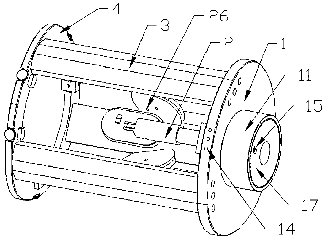
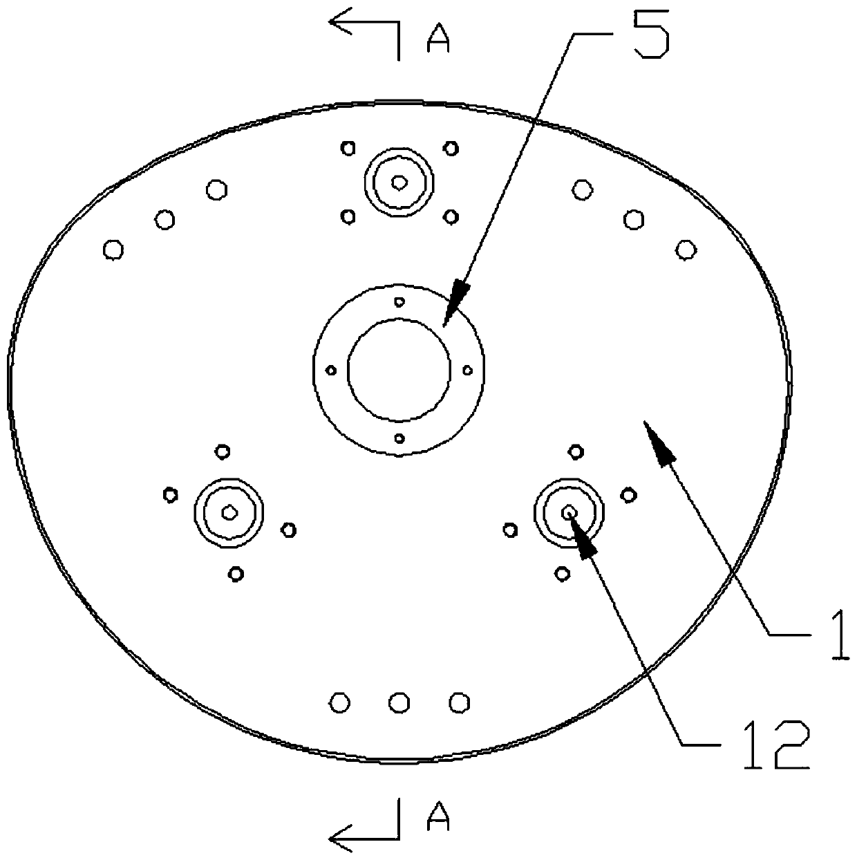
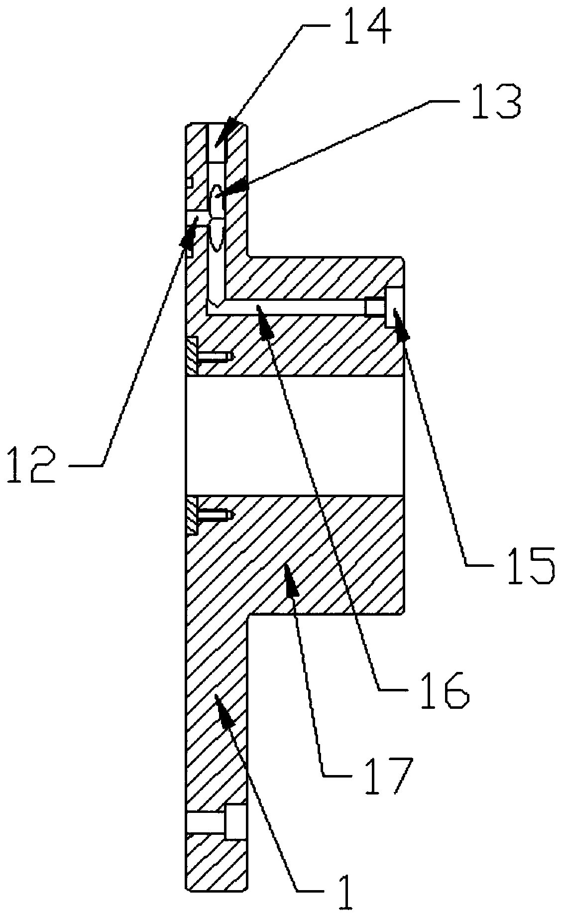
[0023] Such as Figure 1 to Figure 5 As shown, a radome vacuum adsorption fixture includes a fixture body, and the fixture body is composed of at least three adsorption assemblies 2; the adsorption assembly 2 includes a suction cup 21 and an air cylinder; the bottom surface of the suction cup 21 is provided with an air inlet 26 , the top surface is provided with a suction cup trachea joint 22 communicating with the air inlet 26; the cylinder body of the gas cylinder is provided with a gas cylinder trachea joint 23, one end of the gas cylinder is hinged with the top surface of the suction cup 21, and the other end is fixed on the bottom surface of the support frame 1; The top surface of the support frame 1 has a protruding base 17, and the bottom surface of the support frame 1 is provided with three supports 3 surrounding the outside of the adsorption assembly 2, and the bottom surface is also provided with air holes 12 corresponding to the holes at the bottom of the gas cylinde...

Embodiment 2

[0027] In order to avoid that the sucker and the radome are not firmly adsorbed, the gas cylinder includes a first cylinder body 24 and a second cylinder body 25, the first cylinder body 24 is provided with a gas cylinder trachea connector 23, one end of which is hinged to the top surface of the suction cup 21, The other end is slidingly connected with the second cylinder 25 , and a compression spring is sleeved between the second cylinder 25 . When the air compressor is vacuuming, the air pressure in the air cylinder decreases, but due to the support of the pressure spring, the first cylinder and the second cylinder cannot slide relative to each other to contract. When the air pressure in the air cylinder is low to a certain level, the external air pressure can overcome the elastic force of the compression spring to compress the compression spring, so that the first cylinder body shrinks towards the second cylinder body, which proves that the vacuum degree in the air cylinder ...

Embodiment 3

[0030] Such as Figure 6 As shown, in order to speed up the center alignment speed of the clamp and the radome, the outer ring of the collar 4 is provided with six sets of grooves opposite to the inner ring, and the grooves on the outer ring are provided with an adjusting screw 41, and the adjusting screw 41 is connected with the pressure block 42 arranged on the groove of the inner ring through the through holes on the bottom surface of each group of grooves. When the ring is placed outside the radome and the six pressure blocks are in contact with the surface of the radome, turn the six adjusting screws respectively to change the position of the pressure blocks in the inner ring, and then let the pressure blocks push the radome to move in the ring , until it is aligned with the center of the jig, and then the pressing blocks are clamped with the radome, and then the vacuuming work is carried out.

[0031] By adjusting the position of the screw rod and the pressing block, th...


PUM


Abstract

The invention discloses a vacuum adsorption fixture for a radome. A fixture body is at least composed of three adsorption assemblies. Each adsorption assembly comprises a suction cup and an air cylinder, wherein the bottom face of the suction cup is provided with air inlet holes, one end of the air cylinder is hinged to the top face of the suction cup, and the other end of the air cylinder is fixed to the bottom face of a supporting frame; the top face of the supporting frame is provided with a projecting pedestal, the bottom face of the supporting frame is provided with three supporting pieces which surround the adsorption assembly, and the bottom face of the supporting frame is also provided with air holes corresponding to hole positions at the bottom of the air cylinder; the other end of the supporting frame is jointly fixed to a lantern ring; the air holes communicate with air channels in the supporting frame; the air channels jointly intersect and penetrate through a main air channel, and air channel end openings, leading to the edge of the supporting frame, of the air channels are provided with air plugs; and the main air channel communicates with an extraction opening in thepedestal. According to the vacuum adsorption fixture for the radome, the radome cannot be damaged in the clamping process, and the fixture can be rapidly flushed to the center of the radome.

Description

technical field [0001] The invention relates to the field of clamps, in particular to a vacuum adsorption clamp for a radome. Background technique [0002] The radome is a typical structurally integrated component, which has strict requirements on shape, wall thickness and electrical performance, so it puts forward high requirements for the stability of the clamping during processing. In the existing radome processing engineering, mechanical clamping is mostly used. The head of the radome is supported by a nylon block, and the tail is used to cooperate with the nylon block to compress the axial and circumferential directions of the radome. The existing mechanical clamping method has high requirements for installers, and improper clamping force may cause damage to the surface of the radome. Every time when clamping, the center must be found manually, which wastes a lot of processing time. The vacuum adsorption clamping method uses atmospheric pressure to compress the workp...

Claims


Application Information

Patent Timeline
Patent Type & Authority Applications(China)
IPC IPC(8): B23Q3/08
CPCB23Q3/088
Inventor 林彬于富侃李河林侴毅隋天一
Owner TIANJIN UNIV
Why Eureka
Try Eureka