Desilting structure and hydraulic engineering desilting device

A technology for water conservancy projects and dredging devices, which is applied in the directions of earth movers/shovels, mechanically driven excavators/dredgers, construction, etc. It can solve the damage of suction pumps, scrapped water conservancy facilities, and easily blocked pipelines, etc. problem, to achieve the effect of strong reliability

Inactive Publication Date: 2019-07-09
聂海涛
View PDF8 Cites 4 Cited by
  • Summary
  • Abstract
  • Description
  • Claims
  • Application Information

AI Technical Summary

Problems solved by technology

[0003] At present, the rivers in cities and towns are not treated in time due to the perennial sedimentation and silt, which leads to the scrapping of some water conservancy facilities. Once a flood occurs, there will be serious consequences, which brings great difficulty to the water

Method used


Image

  • Desilting structure and hydraulic engineering desilting device
  • Desilting structure and hydraulic engineering desilting device
  • Desilting structure and hydraulic engineering desilting device

Examples


Embodiment 1

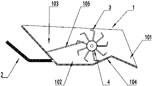
[0021] see Figures 1 to 2 , In the embodiment of the present invention, a dredging structure includes a bucket body 1 and a feeding claw 3. The bucket body 1 includes a feeding part 101, a connecting part 104 and a mud storage part 102 connected in sequence. The bottom of the feeding part 101 is inclined and the bottom of the mud storage part 102 is set horizontally. It enters into the mud storage part 102 through the connecting part 104 for storage, and the feeding claws 3 are fixed on the drum 4 . A plurality of the feeding claws 3 are distributed along the radial and circumferential directions of the drum There is a gap between the two feeding claws 3. The feeding claws 3 are of L-shaped structure, which is convenient for picking up stones and large-volume impurities in the sludge, and at the same time, it will not affect the normal movement of the sludge. The outer edge is opposite to the feeding part 101. Due to the angle setting of the feeding part 101, the sludge will...

Embodiment 2

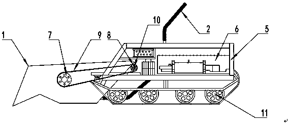
[0026] see image 3 , In the embodiment of the present invention, on the basis of the above embodiment, a dredging device for water conservancy projects is also proposed, which includes a device body, and also includes a dredging structure installed at the front end of the device body as described in the above embodiment.

[0027] Specifically, the device body includes a vehicle body 5 and a crawler wheel 11 installed on the vehicle body 5 . The crawler wheel 11 is used as a traveling device, which has wide adaptability. Of course, the vehicle body 5 is provided with a drive for driving the crawler wheel 11 . Mechanism, a drive motor 10 is installed on the vehicle body 5, and a driving pulley 8 is installed at the output end of the driving motor 10. The driving pulley 8 is connected with the driven pulley 7 at the shaft end of the drum 4 through the synchronous belt 9 to realize the drum. 4 and the rotation of the feeding claw 3, at the same time, a suction pump 6 connected wi...


PUM


Abstract

The invention discloses a desilting structure and a hydraulic engineering desilting device and belongs to the technical field of hydraulic engineering. The desilting structure comprises a bucket bodyand prodding claws. The bucket body comprises a feeding portion, a connecting portion and a silt storage portion which are connected in sequence. The bottom of the feeding portion is arranged obliquely. The bottom of the silt storage portion is arranged horizontally. The highest end position of the feeding portion and the silt storage portion are connected through the connecting portion. The prodding claws are fixed to a drum. The multiple prodding claws are distributed in the radial and circumferential directions of the drum. A gap exists between every two adjacent prodding claws. The prodding claws are each of an L-shaped structure. The outer edges of the prodding claws are opposite to the feeding portion. An impurity portion is arranged on the upper portion of the silt storage portion.An oblique partition plate is arranged between the impurity portion and the silt storage portion. The top end of the partition plate is opposite to the outer edges of the prodding claws. The desiltingstructure and the hydraulic engineering desilting device have the beneficial effects that when desilting is performed, silt is separated from stones, large-size impurities and the like inside, separated storage is achieved, the stones, large-size impurities and the like in the silt are prevented from damaging equipment or the device in the moving process, and the reliability is high.

Description

technical field [0001] The invention relates to the technical field of hydraulic engineering, in particular to a dredging structure and a dredging device for hydraulic engineering. Background technique [0002] A water conservancy project is a project built for the purpose of controlling and deploying natural surface water and groundwater to achieve the purpose of eliminating harm and increasing profits. Also known as water engineering. Water is an indispensable and precious resource for human production and life, but its natural state does not fully meet human needs. Only by building water conservancy projects can we control water flow, prevent flood disasters, and adjust and distribute water to meet the needs of people's lives and production for water resources. Water conservancy projects require the construction of different types of hydraulic structures such as dams, embankments, spillways, sluice gates, water inlets, channels, ferries, rafts, fishways, etc., to achiev...

Claims


Application Information

Patent Timeline
IPC IPC(8): E02F5/28E02F3/88E02F3/90E02F3/94E02F3/92E02F7/04E02F7/06E02F7/10
CPCE02F3/88E02F3/90E02F3/92E02F3/94E02F5/28E02F7/04E02F7/06E02F7/10
Inventor 聂海涛段媛张刚孔锡鲁李鹏秦序东周康鹿文凯郑光辉许延霄
Owner 聂海涛
Why Eureka
Try Eureka