Binocular distance measurement method and system

A binocular ranging and binocular camera technology, applied in the field of computer vision, can solve the problems of high equipment requirements, inability to ensure consistent focal length of zoom cameras, and high threshold for the use of binocular ranging technology

Active Publication Date: 2019-07-09
WUHAN TEXTILE UNIV +1
View PDF12 Cites 2 Cited by
  • Summary
  • Abstract
  • Description
  • Claims
  • Application Information

AI Technical Summary

Problems solved by technology

[0003] At present, the threshold for the use of binocular distance measurement technology is still high, and the requirements for equipment are also high. One of the very important requirements is that the focal lengths of the two cameras used by the binocular camera must be the same or approximately the same, and the focal length of the zoom camera is Unable to ensure consistency, resulting in limited application of binocular ranging, which is not conducive to the further development of binocular ranging

Method used


Image

  • Binocular distance measurement method and system
  • Binocular distance measurement method and system
  • Binocular distance measurement method and system

Examples


no. 3 example

[0094] According to the third embodiment provided by the present invention, a binocular ranging method, on the basis of the second embodiment above, step S250 is based on the corner point information of the first polygon and the second polygon , calculating the scaling factor between the first checkerboard calibration image and the second checkerboard calibration image specifically includes:

[0095] acquiring the coordinates of each corner point of the first polygon and the second polygon;

[0096] defining that the starting point coordinates of the first polygon and the second polygon are consistent;

[0097] Substituting the coordinates of the corner points of the first polygon and the second polygon into formula (1), solving to obtain b 11 , b 12 , b 13 , b 21 , b 22 , b 23 , b 31 , b 32 , b 33 ;

[0098] put the b 11 , b 12 , b 13 , b 21 , b 22 , b 23 , b 31 , b 32 , b 33 Substitute into formula (2), and solve to obtain the scaling factor;

[0099] ...

no. 6 example

[0150] According to the sixth embodiment provided by the present invention, a binocular ranging method includes:

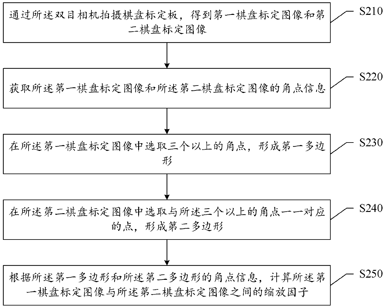
[0151] S301 Use the binocular camera to photograph the checkerboard calibration board to obtain a first checkerboard calibration image and a second checkerboard calibration image;

[0152] Specifically, this step is required to correspond to the positions of the left and right cameras, and it must be ensured that the imaging planes of the two cameras remain approximately on the same horizontal plane.

[0153] During the image acquisition process of the checkerboard calibration, the checkerboard calibration plate should be kept parallel to the camera imaging plane as much as possible, but it needs to constantly move its position or rotate around the z-axis to ensure that there are enough different fields of view. This point is the focus of this study. It is a crucial step in improving the algorithm. If the checkerboard calibration plate and the imaging plane cannot...


PUM


Abstract

The invention relates to the field of computer vision, and discloses a binocular distance measurement method and system. The method disclosed by the invention comprises the steps of: shooting a to-be-measured real object by a binocular camera to obtain a first real object image and a second real object image; according to a precalculated zoom factor, carrying out focal length correction on the first real object image or the second real object image so a to reduce a focal length difference between the first real object image and the second real object image; and according to the first real object image and the second real object image which are obtained after focal length correction, calculating a distance from the to-be-measured real object to the binocular camera. According to the invention, before binocular distance measurement, by utilizing a focal length correction algorithm, images used for binocular distance measurement are processed to correct left and right images with different focal lengths originally and enable the focal lengths of the left and right images to be approximately consistent, so that when binocular distance measurement is carried out, a problem of inconsistent focal length of the camera does not need to be focused, thereby not only saving time and labor, but also enlarging an application environment of binocular distance measurement and reducing use conditions and an equipment threshold of binocular distance measurement.

Description

technical field [0001] The invention belongs to the technical field of computer vision, in particular to a binocular ranging method and system. Background technique [0002] As the cornerstone of the binocular vision system, the binocular distance measurement technology plays an important role in promoting computer vision system-based augmented reality technology (AR technology), virtual reality technology (VR technology), artificial intelligence technology (AI technology) and other current hottest technologies. Cutting-edge developments in the computer field play a huge role. Therefore, research, improve and perfect binocular ranging technology, expand the application scenarios and applicable environments of binocular ranging technology, improve the ranging accuracy of binocular ranging technology, and reduce the threshold of using binocular ranging technology. For computer vision research The development of the direction, as well as the development of the entire computer ...

Claims


Application Information

Patent Timeline
Patent Type & Authority Applications(China)
IPC IPC(8): G01C3/00
CPCG01C3/00
Inventor 彭涛王东旭刘军平姜明华胡新荣何儒汉陈常念吴忠华
Owner WUHAN TEXTILE UNIV
Why Eureka
Try Eureka