

A dual-wavelength laser common optical path transmitting system and method
A dual-wavelength laser and emission system technology, which is applied in the direction of lasers, phonon exciters, laser components, etc., can solve problems such as complex emission systems, and achieve the effects of simple operation, stable cost, and low cost
Inactive Publication Date: 2013-07-10
CHINA WEAPON EQUIP RES INST
View PDF0 Cites 0 Cited by
- Summary
- Abstract
- Description
- Claims
- Application Information
AI Technical Summary
Problems solved by technology
Because of the complexity of the launch system,
Method used
View moreImage
Smart ImageViewing Examples

Examples
Embodiment Construction
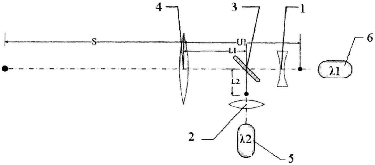
[0035] f2 is the focal length of the incident ray of reflected light relative to the convex lens 2.
[0045]
[0048]
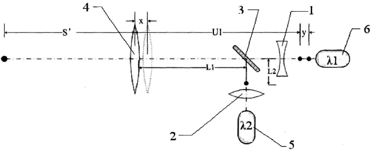
[0049] Micro-adjust the concave lens 1, it can be imaged at the target from the launch system S.
[0051]
[0053]
[0054]
[0055]
[0057] f'2 is the focal length of the incident ray of reflected light relative to the emitting lens group 4.
[0059]
[0060] Simultaneously, the position y to be moved by the concave lens 1 can also be calculated according to formula (6). According to formula (7), it can be calculated
Login to View More PUM
 Abstract
The invention relates to the field of vehicle-mounted high-power fiber laser design, and specifically discloses a dual-wavelength laser common optical path emission system and method, which can be effectively applied in high-power laser emission systems, and are different from the current method of adding lenses of different materials to eliminate dispersion. Applicable, the present invention does not need to increase the lens, and only needs to slightly move the related parts to realize dispersion elimination for the common optical path of the dual-wavelength laser. , The focal length is consistent, and the effect of pointing and damage is consistent. Furthermore, when the lens is coated, the position of the main laser should be selected according to the coating conditions and λ1, λ2 and other conditions to ensure the highest reflectivity and transmittance.
Description
A dual-wavelength laser common optical path emission system and method Technical field The invention belongs to the field of vehicle-mounted high-power fiber laser design, be specifically related to a kind of common optical path emission system and its method. Background technique Various concave-convex mirrors in the launch system have different refractive indices to the main laser and the aiming laser, thereby producing chromatic aberration, such as Without processing, the aiming light and the main laser cannot be focused on the target position at the same time. At present, there are many ways to eliminate chromatic aberration. The most important method is to use a lens group to eliminate chromatic aberration. The lens group is composed of lenses with different refraction and scattering properties, but in Adding multiple lenses to the vehicle-mounted high-power fiber laser launch system to eliminate chromatic aberration will obviously produce more effects, which wil...
Claims
Login to View More Application Information
Patent Timeline
 Patent Type & AuthorityPatents(China)
IPC IPC(8): H01S3/101
Inventor李伟杨宁崔瑞祯周存昌武子淳
OwnerCHINA WEAPON EQUIP RES INST