
Used for servo system resonance suppression, trap parameter optimization method, system and medium

A servo system and resonance suppression technology, applied in the direction of suppressing motor vibration control, estimation/correction of motor parameters, etc., can solve the problems of phase lag, reducing the stability of servo system, and inaccurate parameters.

Active Publication Date: 2021-01-26
SHENZHEN HPMONT TECH
View PDF5 Cites 0 Cited by
  • Summary
  • Abstract
  • Description
  • Claims
  • Application Information

AI Technical Summary

Problems solved by technology

[0004] When the inventor implemented the mechanical resonance suppression of the servo system, he found that a notch filter was inserted in series between the speed loop and the current loop of the servo drive system, thereby reducing the gain at the resonance frequency and achieving the effect of suppressing mechanical resonance. Using the notch filter It is necessary to determine the notch parameters beforehand. The notch parameters will determine the performance of the notch filter. Good parameters can enable the notch filter to suppress resonance. Bad parameters will reduce the stability of the servo system and affect the normal operation of the motor.
The notch filter can be divided into two-parameter notch filter and three-parameter notch filter according to the different notch parameters. The notch parameters that need to be determined before using the two-parameter notch filter are center frequency and notch bandwidth. The notch parameters that need to be determined before the filter include center frequency, notch bandwidth and notch depth. Although the parameters of the two-parameter notch filter are few and easy to adjust, it will introduce a large phase lag and poor stability. The methods include manual setting and automatic calculation. At present, it will take a certain amount of time and energy for technicians to manually set the notch filter. If the notch parameters are determined by automatic calculation, it is easy to choose an inappropriate algorithm. The calculation speed is slow, the calculated parameters are inaccurate, etc.

Method used


Image

  • Used for servo system resonance suppression, trap parameter optimization method, system and medium
  • Used for servo system resonance suppression, trap parameter optimization method, system and medium
  • Used for servo system resonance suppression, trap parameter optimization method, system and medium

Examples


Embodiment 1

[0057] An embodiment of the present invention provides a servo system, including an encoder 01, a control unit 02, a speed loop 03, a current loop 04, a power drive device 05 and a servo motor 06, which will be described in detail below.

[0058] The encoder 01 is used to collect the rotational speed of the servo motor 06 .

[0059] The control unit 02 is used to determine, according to the collected rotational speed, when resonance occurs at the current moment, to start at least one notch filter, and to determine the notch parameters of the started notch filter through the notch parameter optimization method as described in the present invention .

[0060] The speed loop 03 is used to adjust its own output signal after the notch filter is enabled.

[0061] The current loop 04 is used to adjust its own input signal after the trap filter is enabled.

[0062] The power driving device 05 is used for receiving the signal output by the current loop 04 and outputting a driving sig...

Embodiment 2

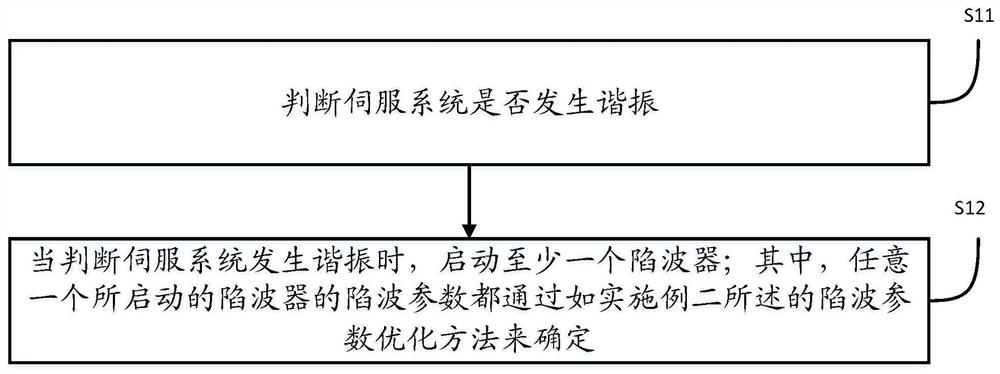
[0074] An embodiment of the present invention provides a method for suppressing resonance in a servo system. The method for suppressing resonance in a servo system is executed internally by the controller, or is executed by a control terminal device outside the control system of the servo motor 06. In servo system resonance suppression method. like figure 2 As shown, the method may include steps S11 to S12, which will be described in detail below.

[0075] Step S11: Judging whether the servo system has resonance.

[0076] Step S12: When it is judged that resonance occurs in the servo system, activate at least one wave trap; wherein, the trap parameters of any activated wave trap are determined by the trap parameter optimization method of the present invention.

[0077] Further, the starting at least one notch filter includes: sequentially starting a preset number of notch filters, wherein after starting one notch filter and operating at the optimized notch parameter, if it is...

Embodiment 3

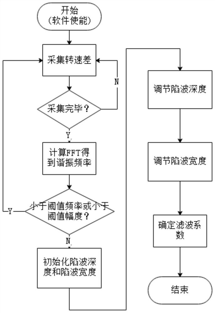
[0082] see Figure 4 , the embodiment of the present invention provides a notch parameter optimization method for servo system resonance suppression, the parameter optimization method for servo system resonance suppression is executed internally by the controller, or the servo motor 06 controls the system outside The control terminal equipment of the control terminal implements the parameter optimization method for servo system resonance suppression. like Figure 4 As shown, the method may include a step of acquiring a threshold S21, a step of determining a filter coefficient equation S22, a step of acquiring a ratio S23, and a step of optimizing a second notch parameter S24, which will be described in detail below.

[0083] Threshold acquisition step S21: Acquire the amplitude threshold corresponding to the maximum resonance frequency when the servo system has no mechanical resonance. In one embodiment, see Figure 5 , the threshold obtaining step S21 can be obtained throu...


PUM


Abstract

Resonance suppression and notch parameter optimization methods for servo systems, a system and a medium are provided. The notch parameter optimization method comprises the following steps: obtaining an amplitude threshold corresponding to the maximum resonance frequency of a servo system under the condition of no mechanical resonance; determining the equation of a filter coefficient, wherein the filter coefficient is the coefficient of a difference equation corresponding to the transfer function of a notch; optimizing a ratio according to a preset sampling frequency, a rotational speed difference set obtained by the sampling frequency, the amplitude threshold and the equation of the filter coefficient, wherein the ratio is the ratio of a first notch parameter to a second notch parameter; and finally, optimizing the first notch parameter and the second notch parameter according to the optimized ratio, the sampling frequency, the rotational speed difference set, the amplitude threshold and the equation of the filter coefficient. Thus, optimized notch parameters are obtained. An automatic notch parameter setting scheme is presented. The notch parameters can be adjusted continuously based on the amplitude threshold, and the notch parameters can be set efficiently.

Description

technical field [0001] The invention relates to the technical field of mechanical control, in particular to a method, system and medium for suppressing mechanical resonance of a servo system. Background technique [0002] The servo system is a feedback control system used to accurately follow or reproduce a certain process, and an automatic control system that enables the output controlled quantities such as the position, orientation, and state of an object to follow any change in the input target (or given value). A typical servo system consists of a control unit, a power drive device, a servo motor and a feedback device. The control unit mainly implements various control algorithms to meet the required control performance and functions; the power drive device converts electrical energy into motor kinetic energy according to the control characteristics. , The servo motor is an engine that controls the operation of mechanical components, and the feedback device uses a positi...

Claims


Application Information

Patent Timeline
Patent Type & Authority Patents(China)
IPC IPC(8): H02P23/04H02P23/14
CPCH02P23/04H02P23/14
Inventor 袁飞平
Owner SHENZHEN HPMONT TECH
Learn More