Dispersing device for coupled separation of oil and sand of lubricating oil

A dispersing device and lubricating oil technology, which is applied in the direction of filtration separation, separation methods, chemical instruments and methods, etc., can solve the problems that the dispersion effect cannot be guaranteed, and the lubricating oil cannot meet the standards, so as to achieve the effect of ensuring high efficiency and ensuring recovery efficiency

Pending Publication Date: 2019-07-12
HEILONGJIANG LANDE ULTRASONIC TECH CO LTD
View PDF7 Cites 3 Cited by
  • Summary
  • Abstract
  • Description
  • Claims
  • Application Information

AI Technical Summary

Problems solved by technology

However, the equipment cannot ensure the dispersion effect through secondary dispersion, so that the lubricating oil that needs to be recovered cannot meet the standard

Method used


Image

  • Dispersing device for coupled separation of oil and sand of lubricating oil
  • Dispersing device for coupled separation of oil and sand of lubricating oil
  • Dispersing device for coupled separation of oil and sand of lubricating oil

Examples


specific Embodiment approach 1

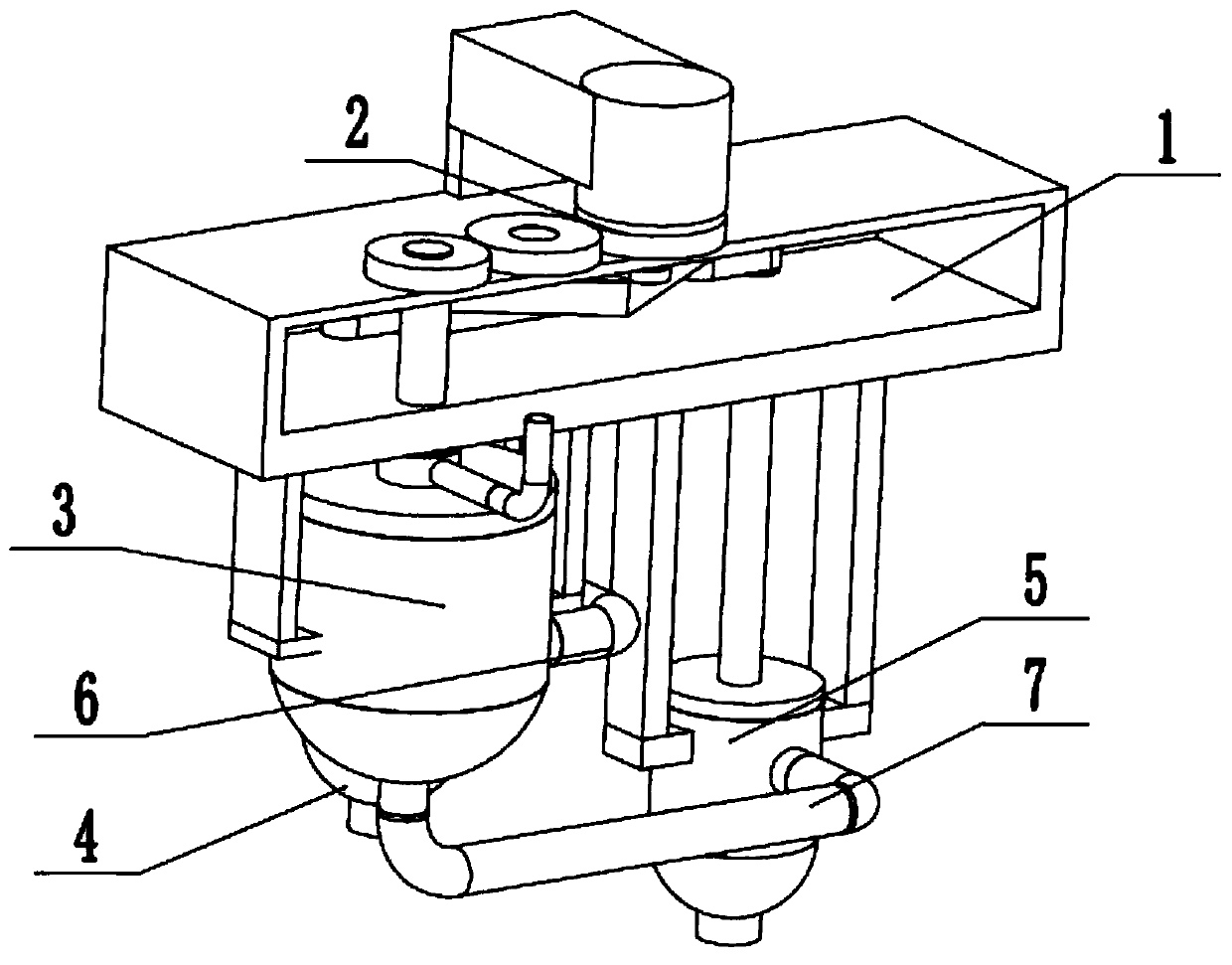
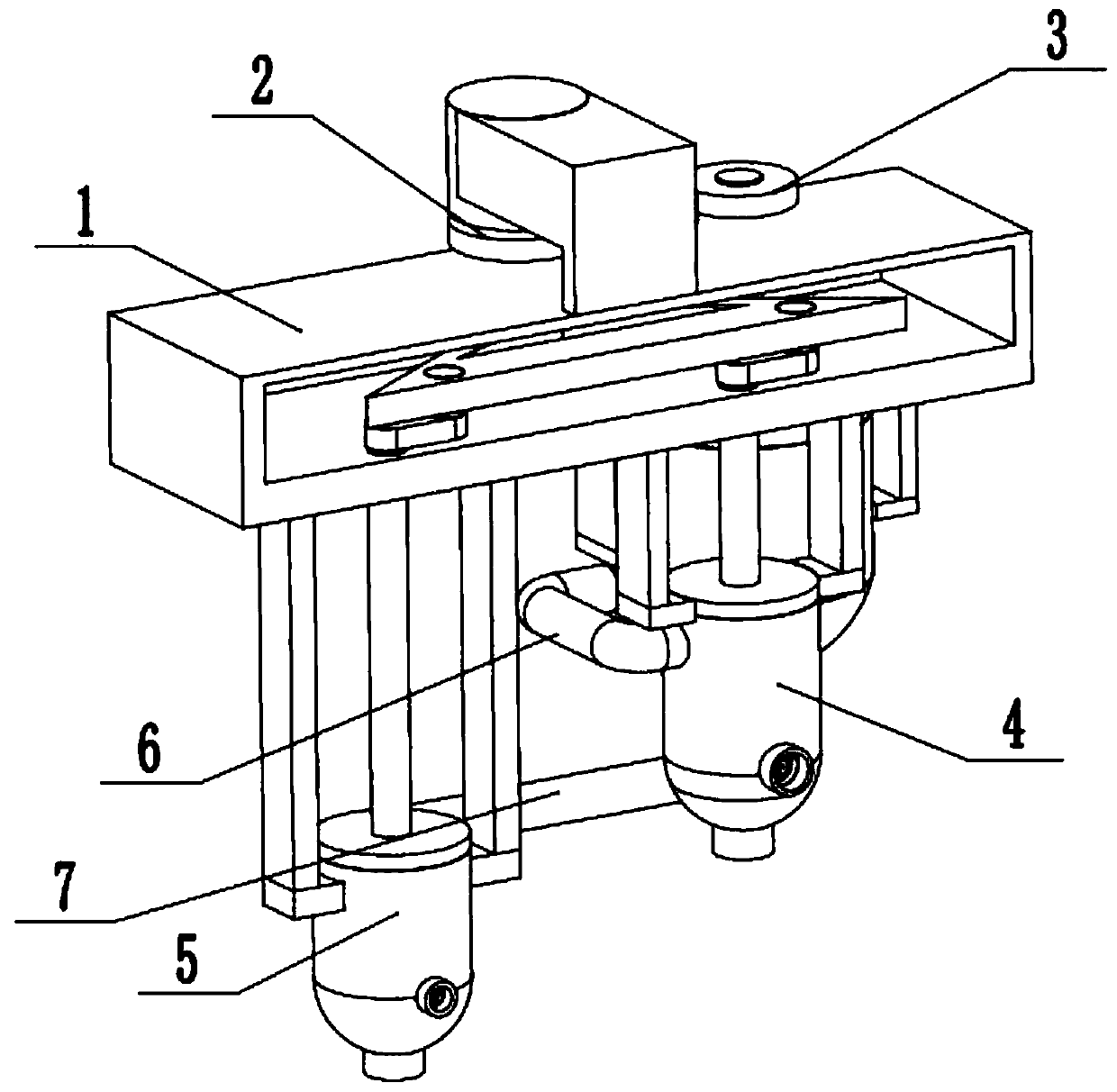
[0031] Such as Figure 1 to Figure 11 As shown, a dispersing device for coupling and separating lubricating oil, oil and sand, including a fixed base 1, a drive agitator 2, a centrifugal filter 3, a secondary oil filter agitator 4, a secondary sand filter agitator 5, and an oil separation connection Rod 6 and sand separation connecting pipe 7, the driving agitator 2 is fixedly connected to the upper end of the fixed base 1, the driving agitator 2 is rotatably connected in the fixed base 1, and the driving agitator 2 is engaged with the centrifugal filter 3 Transmission, the centrifugal filter 3 is connected to the secondary oil filter agitator 4 through the oil separation connecting rod 6, the centrifugal filter 3 is connected to the secondary sand filter agitator 5 through the sand separation connecting pipe 7, the centrifugal filter 3, and the secondary oil filter are stirred The upper ends of the device 4 and the secondary sand filter agitator 5 are fixedly connected to the...

specific Embodiment approach 2

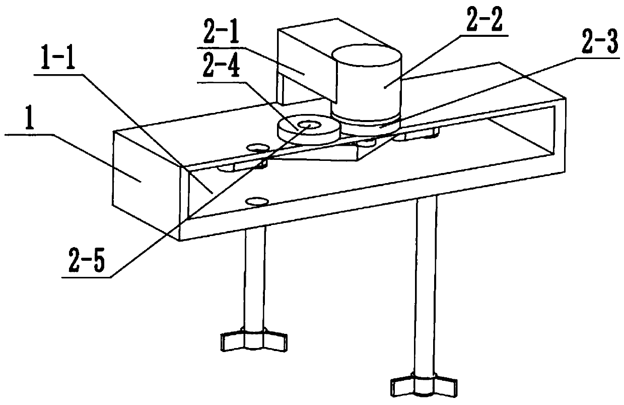
[0033] Such as Figure 1 to Figure 11 As shown, this embodiment further describes the first embodiment, and the fixed base 1 is provided with a movable groove 1-1 that runs through from front to back. The fixed base 1 is used for fixing, and the movable slot 1-1 is used for space activities.

specific Embodiment approach 3

[0035] Such as Figure 1 to Figure 11 As shown, this embodiment will further describe the second embodiment. The drive agitator 2 includes a motor holder 2-1, a servo motor 2-2, a main drive gear 2-3, a transmission gear 2-4, and a transmission shaft 2-5, the main drive rod 2-6, the main hinge shaft 2-7, the triangle drive rod 2-8, the left hinge shaft 2-9 and the right hinge shaft 2-10, the motor holder 2-1 is fixedly connected to the fixed base On the seat 1, the servo motor 2-2 is fixedly connected to the motor fixing seat 2-1, the output shaft of the servo motor 2-2 is connected to the fixed base 1 in rotation, and the main drive gear 2-3 is fixedly connected to the servo motor 2- On the output shaft of 2, the left end of the main driving gear 2-3 meshes with the transmission gear 2-4, the transmission gear 2-4 is connected to the transmission shaft 2-5 in rotation, and the transmission shaft 2-5 is fixedly connected to the fixed base 1 The upper end of the main drive rod...


PUM


Abstract

The invention relates to the field of lubricating oil dispersion, in particular to a dispersing device for coupled separation of oil and sand of lubricating oil. The dispersing device comprises a fixed substrate, a driving stirrer, a centrifugal separating filter, a secondary oil filtering stirrer, a secondary sand filtering stirrer, an oil separating connecting rod and a sand separating connecting pipe. The driving stirrer is fixedly connected to the upper end of the fixed substrate and rotatably connected to the interior of the fixed substrate, the driving stirrer is in engaged transmissionto the centrifugal separating filter, the centrifugal separating filter is communicated with a secondary oil filtering stirrer through the oil separating connecting rod, and the centrifugal separatingfilter is connected to the secondary sand filtering stirrer through the sand separating connecting pipe. The dispersing device has the beneficial effects that an oil-sand mixture is centrifugally separated in a non-storage mode, and oil and sand are secondarily stirred and separated independently and successively, so that the efficiency of oil-sand separation is further guaranteed, and the oil-sand separating recovery efficiency is guaranteed.

Description

technical field [0001] The invention relates to the field of lubricating oil dispersion, in particular to a dispersion device for coupling and separating lubricating oil, oil and sand. Background technique [0002] Patent No. CN201010277065.2 discloses a granular material dispersing device. The motor is fixed on the lower part of the motor frame, and the output shaft of the motor passes through the motor frame upwards and is connected to the drive screw; Drive the screw to move up and down in the shaft sleeve; the outer wall of the lifting screw sleeve is provided with a guide groove along its axial direction, and the inner wall of the shaft sleeve is equipped with a vertical guide pin, which is embedded in the guide groove and acts as a Sliding fit; the top of the lifting nut is installed with a top plate, the top plate is a circular flat plate, the plane elastic body is flat on the top surface of the top plate, and the edge of the plane elastic body is clamped on the brac...

Claims


Application Information

Patent Timeline
Patent Type & Authority Applications(China)
IPC IPC(8): B01D36/02
CPCB01D36/02
Inventor 武明杰杜超卢立鑫于家琦张修全单长城李伟
Owner HEILONGJIANG LANDE ULTRASONIC TECH CO LTD
Why Eureka
Try Eureka