Charging gun for new-energy electric vehicle

A technology for electric vehicles and charging guns, which is applied in electric vehicle charging technology, electric vehicles, charging stations, etc., can solve problems such as electric ignition, and achieve the effects of protecting circuits, accelerating heat dissipation, and improving heat flow exchange capacity.

Active Publication Date: 2019-07-12
乐清泰起知识产权服务有限公司
View PDF6 Cites 6 Cited by
  • Summary
  • Abstract
  • Description
  • Claims
  • Application Information

AI Technical Summary

Problems solved by technology

[0005] The purpose of the present invention is to provide a charging gun for new energy electric vehicles with good heat dissipation effect and high-temperature automatic power-off function to solve the problem that the existing charging gun is easy to cause electric fire when charging in a high-temperature environment for a long time

Method used


Image

  • Charging gun for new-energy electric vehicle
  • Charging gun for new-energy electric vehicle
  • Charging gun for new-energy electric vehicle

Examples


Embodiment 1

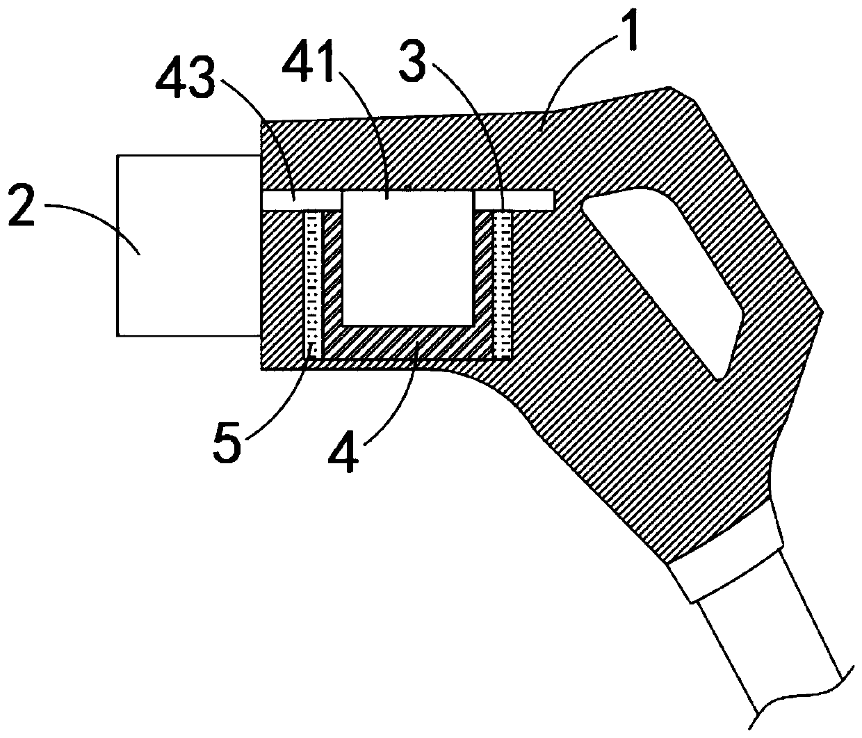
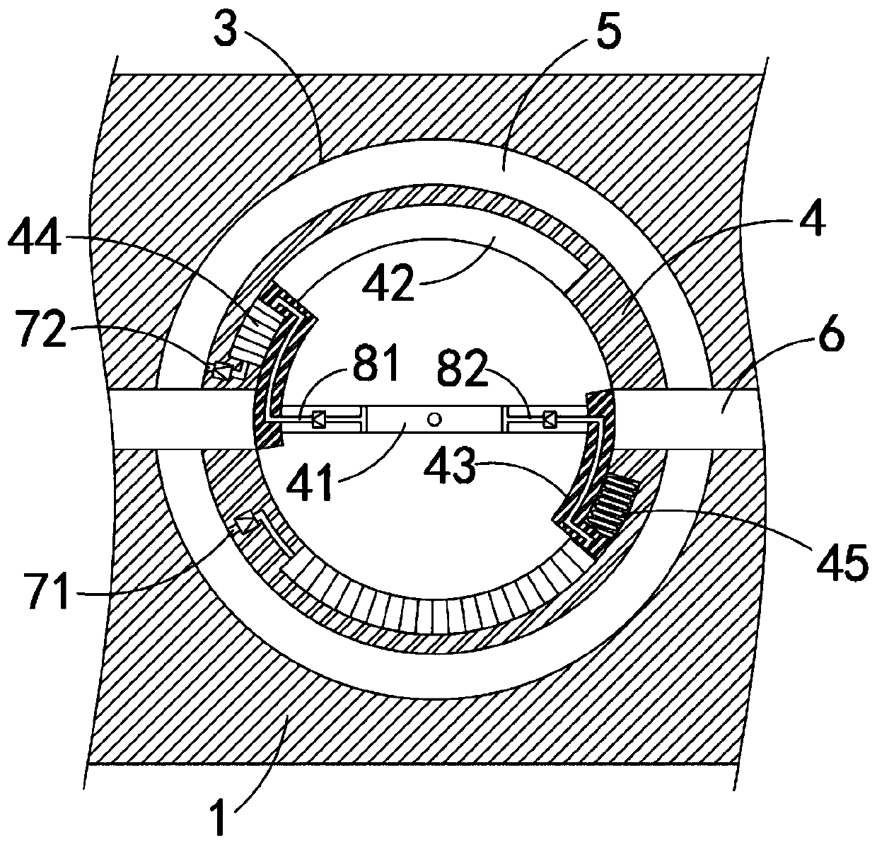
[0036] Such as Figure 1-3 As shown, a charging gun for a new energy electric vehicle includes a gun body 1, a charging head 2 is fixedly connected to the front end of the gun body 1, a cavity 3 is provided in the gun body 1, and an insulating cylinder 4 is fixedly connected to the cavity 3 , the insulating cylinder 4 can be made of insulating materials such as high temperature resistant plastics, a liquid storage chamber 5 is formed between the insulating cylinder 4 and the cavity 3, and the liquid storage chamber 5 is filled with insulating liquid, and the insulating liquid can be transformer oil, and the insulating cylinder 4 Conductive strips 6 are installed on both sides of the tube, and the two conductive strips 6 are electrically connected to the power line and the charging head 2 respectively. Inside the insulating cylinder 4 are:

[0037] Conductive plate 41, conductive plate 41 is rotatably connected with cavity 3, conductive plate 41 can rotate along the axis of ins...

Embodiment 2

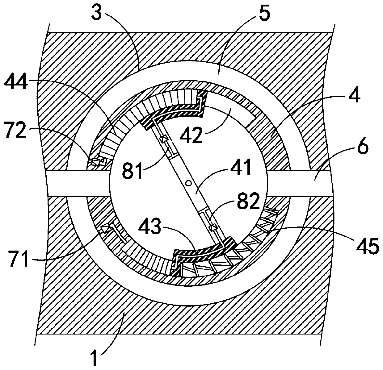
[0048] Such as Figure 4 As shown, the difference between this embodiment and Embodiment 1 is that the internal conveying mechanism includes:

[0049] A one-way liquid inlet pipe 91, the input end of the one-way liquid inlet pipe 91 is connected with the inside of the insulating cylinder 4, and the output end of the one-way liquid inlet pipe 91 is connected with one of the elastic bellows 44;

[0050] One-way liquid discharge pipe 92, the output end of one-way liquid discharge pipe 92 is connected with the inside of insulating cylinder 4, and the input end of one-way liquid discharge pipe 92 is connected with another elastic bellows 44;

[0051] A plurality of circulation holes 10 are evenly distributed on the conductive plate 41 .

[0052] In this embodiment, when the conductive plate 41 rotates, the insulating liquid on both sides of the conductive plate 41 will pass through the plurality of flow holes 10 and become multiple streams, and the multiple streams impact and blen...


PUM


Abstract

The invention belongs to the field of new energy, and particularly relates to a charging gun for a new-energy electric vehicle. The charging gun for the new-energy electric vehicle comprises a gun body, wherein a charging head is fixedly connected to the front end of the gun body, and a cavity is formed in the gun body; an insulating cylinder is fixedly connected into the cavity, and a liquid storage cavity is formed between the insulating cylinder and the cavity; the liquid storage cavity is filled with an insulating liquid, and two conductive strips are correspondingly arranged on the two sides of the insulating cylinder in a penetrating mode; the two conductive strips are correspondingly and electrically connected with a power supply line and the charging head, and the insulating cylinder is internally provided with a conductive plate, two arc-shaped grooves and two conductive blocks; the conductive plate is rotatably connected with the cavity and can rotate along the axis of the insulating cylinder; the two arc-shaped grooves are symmetrically formed in the two sides of the inner side wall of the insulating cylinder; and the two conductive blocks are arc-shaped blocks, the twoarc-shaped blocks are correspondingly and fixedly connected to the two ends of the conductive plate and coincide with the circle center of the insulating cylinder, and the arc-shaped blocks are slidably connected with the inner side wall of the insulating cylinder. According to the charging gun for the new-energy electric vehicle, automatic power off can be realized when the temperature is too high, so that security in the charging process is improved, and a fast heat dissipation effect can be realized.

Description

technical field [0001] The invention belongs to the field of new energy, and in particular relates to a charging gun for a new energy electric vehicle. Background technique [0002] New energy electric vehicles refer to vehicles powered by vehicle-mounted power supplies, driven by motors to drive wheels, and vehicles that meet the requirements of road traffic and safety regulations. They have high energy efficiency and are clean energy sources that cause less pollution to the environment. [0003] During the use of new energy electric vehicles, it is necessary to charge the on-board power supply by connecting the charging pile with the help of a charging gun. The charging gun is completely inserted into the charging port of the car during use. The existing charging gun has long charging time and high current. Therefore, in some high-temperature weather, it is easy to cause the heat at the connector of the charging gun to be too high, and the heat cannot be dissipated in time...

Claims


Application Information

Patent Timeline
Patent Type & Authority Applications(China)
IPC IPC(8): B60L53/16B60L53/302
CPCY02T10/70Y02T10/7072Y02T90/12Y02T90/14
Inventor 吴娟婷
Owner 乐清泰起知识产权服务有限公司
Why Eureka
Try Eureka