
Construction method of foundation pit enclosure within used influence range of pipelines

A technology of influence scope and construction method, applied in infrastructure engineering, excavation, artificial islands, etc., can solve the problems of surrounding people with great influence, many uncontrollable factors, pipelines cannot be interspersed, etc., to achieve small influence and improve stability. , the effect of reducing the number of settings

Active Publication Date: 2019-07-12
RAILWAY TENTH GROUP NORTHWEST ENG
View PDF6 Cites 4 Cited by
  • Summary
  • Abstract
  • Description
  • Claims
  • Application Information

AI Technical Summary

Problems solved by technology

Existing foundation pit enclosure methods require dense pile foundations, resulting in pipelines not being able to penetrate the gaps between the pile foundations, but must be relocated
However, the cost of the pipeline relocation has a relatively large impact on the construction period, the project volume is large, and the pipeline relocation involves water, electricity, gas, communication, etc., which has a great impact on the surrounding people, and there are many uncontrollable factors.

Method used


Image

  • Construction method of foundation pit enclosure within used influence range of pipelines
  • Construction method of foundation pit enclosure within used influence range of pipelines
  • Construction method of foundation pit enclosure within used influence range of pipelines

Examples


Embodiment Construction

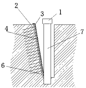
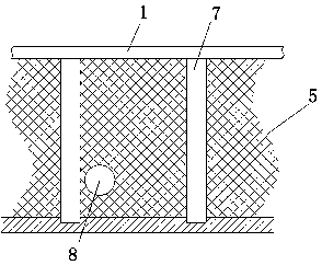
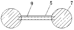
[0030] The present invention is described in detail below in conjunction with accompanying drawing. as attached figure 1 to attach image 3 As shown, a foundation pit enclosure construction method used in the influence range of the pipeline, the steps are as follows:

[0031] Step 1. Excavate deep grooves along both sides of the foundation pit to be excavated. The deep grooves are excavated to expose the pipeline 8 in the earth on both sides of the foundation pit. The side of the deep groove away from the foundation pit is the slope 6.

[0032] Step 2 Set up the enclosure pile 7 in the gap between the pipeline 8 in the deep groove, and set the pile top crown beam 1 with the enclosure pile 7 as the support, and reserve the steel bar joint at the bottom of the pile top crown beam 1.

[0033] Step 3 Lay the reinforced mesh sheet 3 on the surface of the slope 6 .

[0034] Step 4 Nail the reinforced soil nails 2 into the earth along the direction of the vertical slope 6, and wel...


PUM


Abstract

The invention relates to a construction method of a foundation pit enclosure used in the influence range of pipelines. The construction method comprises the steps that deep grooves are excavated alongthe outer sides of the two edges of a foundation pit to be excavated correspondingly, wherein the sides, far away from the foundation pit, of the deep grooves are slope surfaces; an enclosing piles are arranged at gaps of the pipelines in the deep grooves, a pile top crown beam is arranged by taking the enclosing piles as a support, and a steel bar joint is reserved at the bottom of the pile topcrown beam; a retaining wall is arranged on the surfaces of the slope surfaces; the foundation pit is excavated in a layered mode, and at the same time enclosing walls are arranged between every two enclosing piles; and after excavation of the foundation pit is completed, earthwork is backfilled between the retaining wall and enclosing walls. Through the construction of the retaining wall and enclosing walls, the earthwork on the two sides of the foundation pit is reinforced, the arranging number of base piles during the construction of the pile top crown beam is reduced, the pipelines and thefoundation pit enclosure can be arranged alternately, the relocation of the original pipelines is avoided, and the construction method has the advantages that the engineering quantity is effectivelyreduced, the operation is simple, the overall stability of the foundation pit enclosure structure can be effectively improved, the construction progress can be accelerated, the construction cost can be saved, and the influence on water, electricity, gas communication and the like of residents is small.

Description

technical field [0001] The invention relates to the technical field of foundation pit enclosure, in particular to a construction method for foundation pit enclosure within the influence range of pipelines. Background technique [0002] With the development of my country's rail transit construction, the proportion of subway projects is increasing. Pile foundation construction is especially important in subway projects. The construction of subway stations is generally located in the center of the city, and the underground pipelines in the city center are intricate and difficult to relocate. And the time span is long, and large machinery cannot play a role in this environment. [0003] The traditional construction method is roughly the construction method of bored pile: pipeline excavation→pipeline relocation→pile foundation construction→structural construction→pipeline relocation. Existing foundation pit enclosure methods all require intensive setting of pile foundations, resu...

Claims


Application Information

Patent Timeline
Patent Type & Authority Applications(China)
IPC IPC(8): E02D5/22E02D17/04E02D29/02
CPCE02D5/22E02D17/04E02D29/02
Inventor 尚春阳李孟章宋寿兵赵立军张廷许东晓郝红伟蒲赵蔡赵硕
Owner RAILWAY TENTH GROUP NORTHWEST ENG
Learn More