Electric supercharger using waste heat from internal combustion engine and power supply method thereof

An electric supercharging and internal combustion engine technology, which is applied in gas turbine devices, steam engine devices, internal combustion piston engines, etc., can solve the problems of slow engine response, severe electric charge and discharge, and driver's anxiety, reducing the number and setting. Quantity and cost reduction effect

Inactive Publication Date: 2014-08-13
MITSUBISHI HEAVY IND LTD
View PDF7 Cites 11 Cited by
  • Summary
  • Abstract
  • Description
  • Claims
  • Application Information

AI Technical Summary

Problems solved by technology

[0010] At this time, if a large power is used in the electric compressor, the power supply voltage of the electric storage unit will drop, which will adversely affect the operation of other devices and equipment that use the same power supply as the electric storage unit.
[0011] In addition, if the charging and discharging of electric power is intense, the aging of the battery of the power storage unit (in the case of a battery) will be accelerated
[0012] In addition, if a large power is used in the electric compressor, the charge amount of the electric storage unit decreases, the boosting capacity decreases, the response of the engine slows down, and the driver feels uneasy.

Method used


Image

  • Electric supercharger using waste heat from internal combustion engine and power supply method thereof
  • Electric supercharger using waste heat from internal combustion engine and power supply method thereof
  • Electric supercharger using waste heat from internal combustion engine and power supply method thereof

Examples


no. 1 approach

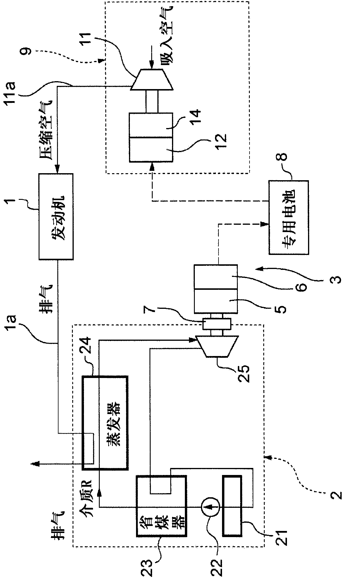
[0068] Shown is an overall schematic configuration diagram related to the electric supercharging device utilizing the waste heat of the engine according to the present invention, and 1 is an engine.

[0069] Exhaust gas discharged from the engine 1 is introduced into a steam cycle device 2 that converts heat of the exhaust gas into rotational energy through an exhaust pipe 1 a. The rotational energy of the steam cycle device 2 drives the first generator 5 via the magnetic coupling 7 as a non-contact joint to perform AC power generation. The alternating current is converted into direct current through the first converter 6 arranged in parallel with the first generator 5 (the first generator 5 and the first converter 6 constitute the first generating device 3 ), and is used as the first storage The battery 8 of the electric device stores electricity.

[0070] Reference numeral 9 denotes an electric supercharger, and the electric supercharger 9 is configured to drive the first c...

no. 2 approach

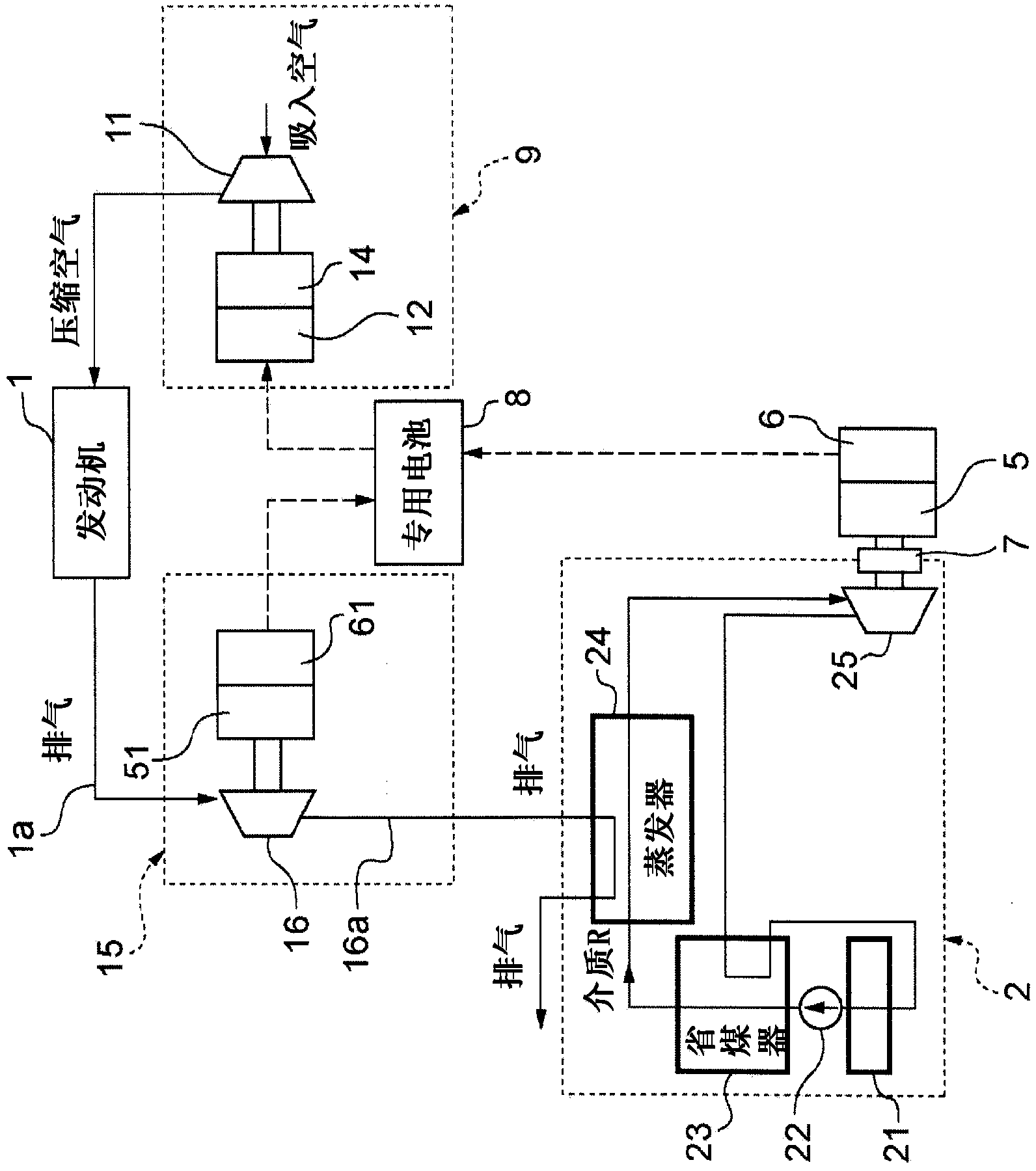
[0099] In this embodiment, the exhaust turbine generator 15 is installed between the steam cycle device 2 and the engine 1 compared to the first embodiment. Therefore, the same reference numerals are assigned to the same parts, and explanations thereof are omitted.

[0100] Exhaust gas discharged from the engine 1 is introduced into an exhaust turbine power generation device 15 as a second power generation device via an exhaust pipe 1 a. Exhaust gas from the exhaust turbine 16 that drives the exhaust turbine generator 15 is introduced into the steam cycle device 2 . The steam cycle device 2 rotationally drives an expander 25 serving as a steam turbine by steam of a liquid medium generated by the heat of the exhaust gas, and drives the first generator 5 to generate electricity. The generated electric current is converted from alternating current to direct current by the first converter 6 and charged to the battery 8 as a dedicated power storage device.

[0101] In addition, t...

no. 3 approach

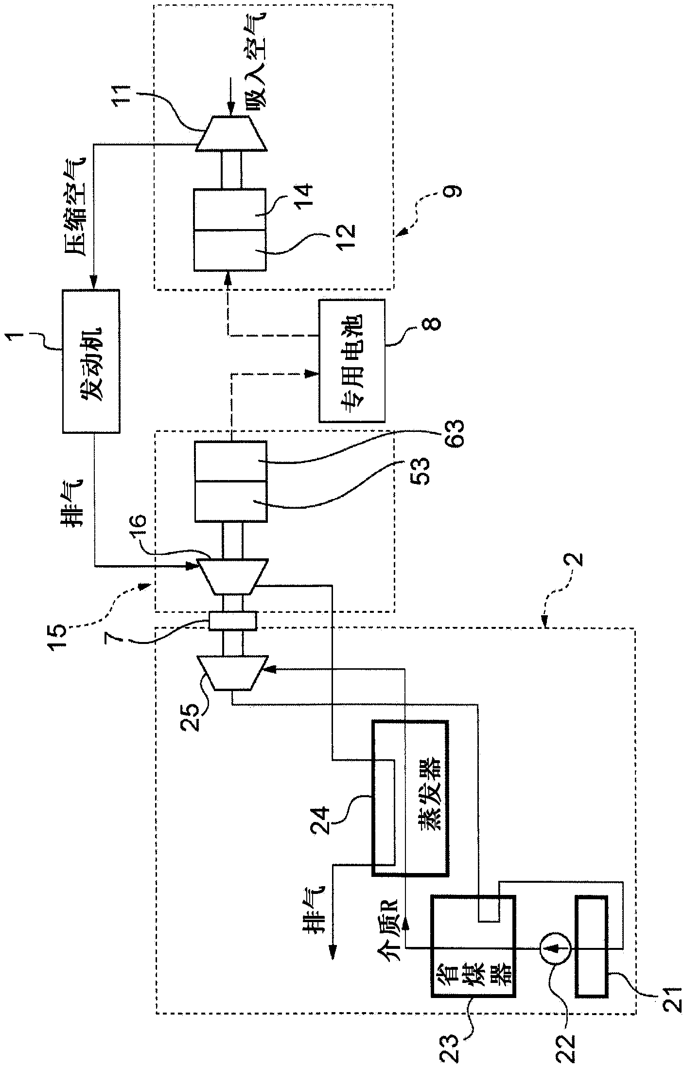
[0108] Compared with the first embodiment, this embodiment is a structure in which the rotation shaft of the expander 25 of the steam cycle device 2 and the rotation shaft of the exhaust turbine generator 15 of the second embodiment are coaxially connected by the magnetic coupling 7 .

[0109] Exhaust gas discharged from the engine 1 is introduced into the exhaust gas turbine generator 15 through the exhaust pipe 1 a. Exhaust gas from the exhaust turbine 16 that drives the exhaust turbine generator 15 is introduced into the steam cycle device 2 . The steam cycle device 2 changes the liquid medium into steam, and the expander 25 is rotationally driven by the steam.

[0110] The exhaust turbine power generation device 15 includes an exhaust turbine 16 rotationally driven by exhaust gas from the engine 1, a third generator 53 provided at the other end side of the rotation of the exhaust turbine 16, and the third generator 53 generating electricity. The current is converted from...


PUM


Abstract

Waste heat from an engine is effectively converted into power and the power is stored in a dedicated power storage device to freely output boost pressure from an electric air compressor so as to improve fuel efficiency, drivability, and exhaust gas purification. The present invention comprises: a steam cycle device (2) which rotates an expander (25) by expanding steam generated by waste heat from an engine (1); a first power generator (5) which is connected to the expander (25) and generates power using torque from the expander (25); a dedicated battery (8) which stores the power that is generated by the first power generator (5); and an electric supercharger (9) which drives a first compressor (11) using a motor (14) driven by the power in the dedicated battery(8) and generates compressed air.

Description

technical field [0001] The present invention relates to an electric supercharger for driving an electric compressor using electric energy generated by waste heat of an internal combustion engine (hereinafter referred to as "engine") and an electric power supply method thereof. Background technique [0002] As a measure for high engine output, energy saving, and exhaust purification, a turbocharger that drives a compressor using exhaust gas from the engine to supercharge intake air is often used. [0003] However, in a turbocharger that drives a turbine by exhaust gas and drives a compressor directly connected to the rotating shaft of the turbine, there is a problem that the exhaust gas of the engine is exhausted until a sufficient amount is exhausted and the compressor performs sufficient supercharging. There is a so-called turbo lag problem that takes time until now. [0004] As a countermeasure against this, a turbocharger with an electric motor that drives a compressor b...

Claims


Application Information

Patent Timeline
Patent Type & Authority Applications(China)
IPC IPC(8): F02B37/00F01K23/10F01N5/02F02B33/34F02B37/04F02B37/10F02B37/16F02B37/18F02B39/10F02B41/10F02D23/00F02D23/02F02D29/06F02G5/02F02G5/04
CPCF02B37/18F02B37/04F01N5/025Y02T10/16F01K25/08Y02T10/144F02B37/16F01K23/065F02B39/10F02D23/00F02B37/00F02G5/02F02B41/10Y02T10/12F02C6/18F01K13/02F01K25/10Y02E20/14Y02E20/16F01K23/10F01N5/02
Inventor 山下幸生安秉一惠比寿干坂本武藏荻田浩司
Owner MITSUBISHI HEAVY IND LTD
Why Eureka
Try Eureka