Fin-tube type heat exchanger

A technology of heat exchangers and pipelines, applied in heat exchange equipment, heat exchangers, water heaters, etc., can solve the problems of reducing heat exchanger efficiency, heat exchange efficiency, and thermal efficiency, etc., and achieve miniaturized manufacturing , Improve heat exchange efficiency and prevent local overheating

Active Publication Date: 2015-09-02
KYUNGDONG NAVIEN
View PDF13 Cites 9 Cited by
  • Summary
  • Abstract
  • Description
  • Claims
  • Application Information

AI Technical Summary

Problems solved by technology

[0006] However, if image 3 As shown, the existing fin-pipe heat exchanger has the following problem: the lower end 10a of the pipe 10 located on the side where the combustion product produced by the combustion of the burner 70 flows into is locally overheated, so that the pipe 10 passes through the pipe 10. Bubbles B are generated in the internal heat medium to cause boiling noise, and foreign substances such as calcium contained in the heat medium are solidified in the stagnant area inside the pipe 10 to significantly reduce the efficiency of the heat exchanger, and in severe cases The problem of damage caused by overheating in this part
Therefore, when the heat transfer fin 20 is processed into a flat plate, the heat exchange efficiency will be reduced in the region after the temperature critical layer formation point B, and if the temperature critical layer formation point B is far away from the origin of the heat transfer fin 20 If the distance between the heat transfer fins 20 is narrowed from the beginning to the end, there is a problem that the thermal efficiency decreases due to the increase in the flow resistance of the combustion product.

Method used


Image

  • Fin-tube type heat exchanger
  • Fin-tube type heat exchanger
  • Fin-tube type heat exchanger

Examples


Embodiment Construction

[0062] Hereinafter, configurations and functions of preferred embodiments of the present invention will be described in detail with reference to the accompanying drawings.

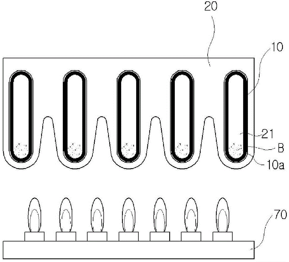
[0063] Figure 6 and Figure 7 is a perspective view of the fin-pipe heat exchanger according to the present invention observed from different angles, Figure 8 for Figure 6 The exploded perspective view of Figure 9 for Figure 6 The A-A line profile.

[0064] The fin-pipe heat exchanger 100 according to the present invention is characterized in that the heat that flows through the inside of the heat medium inflow tube 120a, the tube 110, and the heat medium outflow tube 120b provided so as to pass through the inside of the heat exchanger 100 is The flow of the medium generates turbulence, so as to prevent the boiling of the heat medium and the solidification of foreign matter caused by local overheating, and make the flow of the combustion product passing between the heat transfer fins 150 generate...


PUM


Abstract

The present invention relates to a pin-tube type heat exchanger, comprising: tubes through the inside of which a heat medium flows and which are arranged in parallel with a uniform distance therebetween, so that a combustion product can pass through space between the tubes; and heat transfer fins which are separately coupled to the outer surface of the tubes along the lengthwise direction thereof, so as to be parallel to the direction of flow of the combustion product, wherein inside the tubes a first turbulent flow-generating member is installed for creating turbulence in the flow of the heat medium, wherein the first turbulent flow-generating member comprises a flat plate portion, arranged in the lengthwise direction of the tubes, for dividing the inner space of the tubes into two sides, and first guide pieces and second guide pieces which are protrudingly provided at a tilted angle and are separately and alternately provided along the lengthwise direction of both sides of the flat plate portion.

Description

technical field [0001] The invention relates to a fin-pipe heat exchanger which is combined with heat transfer fins on the outer surface of the pipe to exchange heat between the heat medium flowing inside the pipe and the combustion product. A fin-pipe heat exchanger that suppresses noise and improves thermal efficiency by the turbulent flow of the heat medium flowing inside the tube and the combustion product passing between the heat transfer fins. Background technique [0002] Generally, a heating device has a heat exchanger for exchanging heat between a combustion product generated by combustion of fuel and a heat medium (heating water), thereby performing heating or hot water supply using the heated heat medium. [0003] Existing fin-pipe heat exchangers are composed of pipes combined with heat transfer fins in which the heat medium flows along the inner space, and the heat transfer fins have a shape protruding from the surface of the pipes . [0004] refer to figure ...

Claims


Application Information

Patent Timeline
Patent Type & Authority Applications(China)
IPC IPC(8): F28F1/32F28F9/24
CPCF28D21/0007F28F1/32F28F1/40F28F13/12F28F1/42F24H1/40F28D2021/0024F28D1/05375F28F2215/10F28F9/24F28F13/125F28F1/12
Inventor 李东根
Owner KYUNGDONG NAVIEN
Why Eureka
Try Eureka