Foldable sawtooth punched-plate
A punching plate and sawtooth technology, applied in the field of foldable sawtooth punching plate, can solve the problems such as the inability of the cement intercepting plate to be used, the thickness of the steel protective layer is too large, the positioning of the steel bar is not accurate, and achieves civilized construction, accurate thickness, Overall good effect
- Summary
- Abstract
- Description
- Claims
- Application Information
AI Technical Summary
Problems solved by technology
Method used
Image
Examples
Embodiment 1
[0025] Example 1 is basically as attached figure 1 Shown:
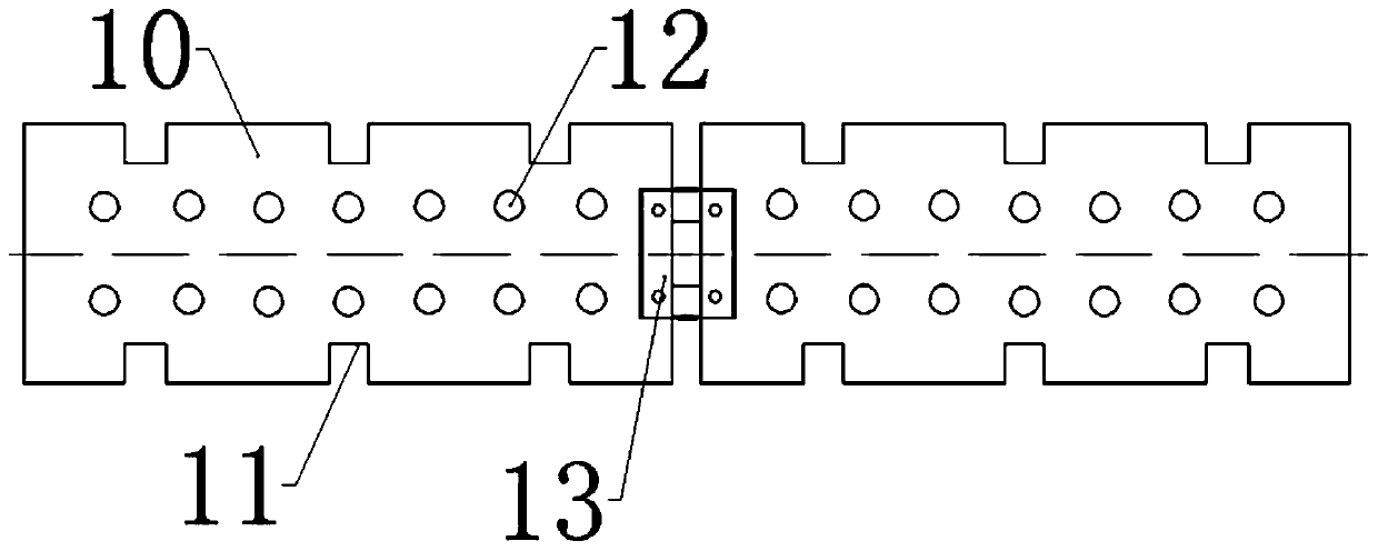
[0026] A foldable serrated punching board, such as figure 1 As shown, it includes two rectangular steel plates 10 and a stainless steel hinge 13. The size of the steel plate 10 is 400×120×3mm. The steel plate 10 is punched with punching holes 12. There are two rows of punching holes 12 in each row. There are 8 holes in each row. It is a circular through hole, the hole diameter of the punching hole 12 is 10mm, and the spacing between the punching holes 12 is 50mm. The two long sides of the steel plate 10 are cut into a zigzag shape, and the teeth 11 on the two long sides correspond to each other. The size of 11 is set to 25×25mm, and the spacing between serrations 11 is 100mm. One of the short sides of the two steel plates 10 is connected by a stainless steel hinge 13. The size of the hinge 13 is 2 inches. The hinge 13 is firmly welded between the two steel plates 10, and the two steel plates 10 and the hinge 13 form a fo...
Embodiment 2
[0030] The difference between embodiment 2 and embodiment 1 is that the punching hole 12 is a rectangular through hole of 20×3mm, and the rectangular through hole makes the flowing mortar into a strip shape. After the steel plate 10 is removed, a strip-shaped rough surface can be naturally formed on the cement, without Picking, the texture formed by rectangular through holes is more natural than the texture formed by circular through holes.
Embodiment 3
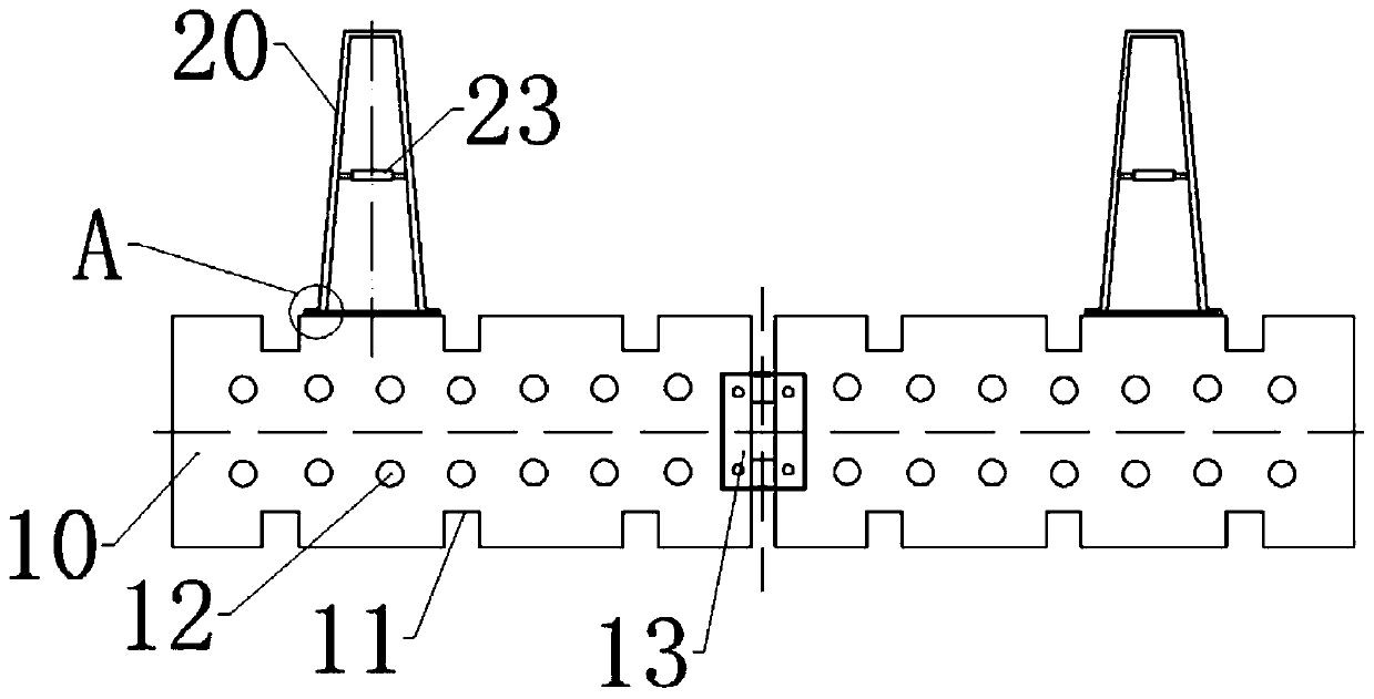
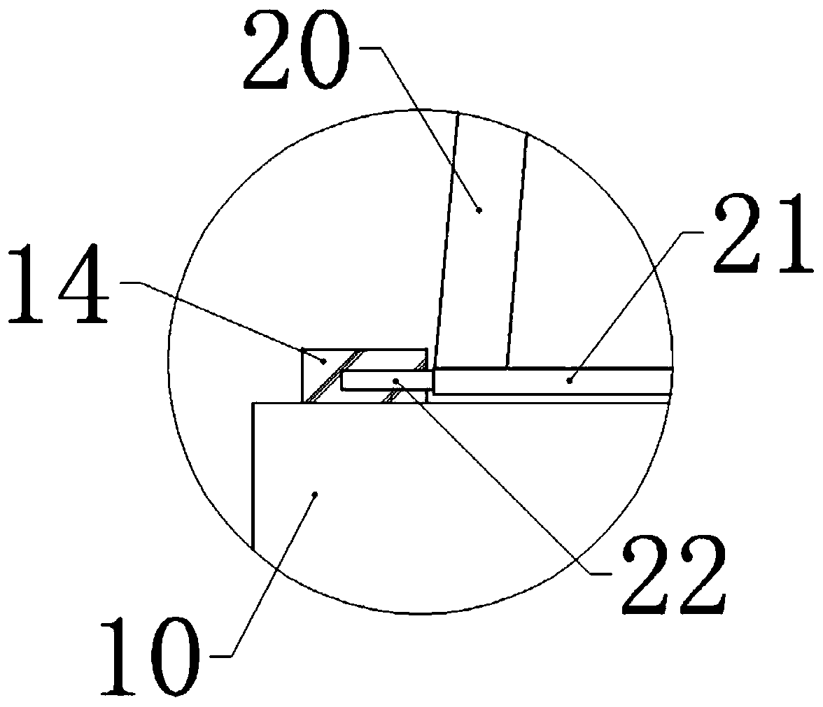
[0032] The difference between embodiment 3 and embodiment 1 is: combination figure 2 with image 3 As shown, two fixing blocks 14 are welded between a pair of adjacent serrations 11 on a long side of the steel plate 10, and a cylindrical blind hole is provided in the fixing block 14, and the openings of the two blind holes are arranged oppositely. A cylindrical rotating rod 21 is connected between the two blind holes. Both ends of the rotating rod 21 are coaxially provided with cylindrical protrusions 22 that match the blind holes. The rotating rod 21 can rotate relative to the fixed block 14. The rotating rod An A-shaped support plate 20 is fixedly connected to 21. The support plate 20 is welded by steel bars. The support plate 20 can follow the rotating rod 21 to rotate relative to the fixed block 14, so that the support plate 20 can act as a diagonal brace. The plate 20 can prevent the steel plate 10 from toppling, and the steel plate 10 does not need to be manually restric...
PUM
 Abstract
Description
Claims
Application Information
 - R&D
- Intellectual Property
- Life Sciences
- Materials
- Tech Scout
- Unparalleled Data Quality
- Higher Quality Content
- 60% Fewer Hallucinations
Browse by: Latest US Patents, China's latest patents, Technical Efficacy Thesaurus, Application Domain, Technology Topic, Popular Technical Reports.
© 2025 PatSnap. All rights reserved.Legal|Privacy policy|Modern Slavery Act Transparency Statement|Sitemap|About US| Contact US: help@patsnap.com


