
Positioning structure for mandrel assembly parts, use method thereof, and impeller dynamic balance testing device

A technology for positioning structures and positioning methods, applied in static/dynamic balance testing, machine/structural component testing, measuring devices, etc., can solve problems such as inability to locate assembly parts, and achieve the effect of improving the scope of application

Pending Publication Date: 2019-07-12
BEIJING XINGJI RONGYAO SPACE TECH CO LTD
View PDF6 Cites 1 Cited by
  • Summary
  • Abstract
  • Description
  • Claims
  • Application Information

AI Technical Summary

Problems solved by technology

[0004] Therefore, the present invention aims to provide a positioning structure and usage method of a mandrel assembly and an impeller dynamic balance test device to solve the problem that the positioning structure in the prior art cannot accurately and firmly position the assembly along the length of the mandrel. question

Method used


Image

  • Positioning structure for mandrel assembly parts, use method thereof, and impeller dynamic balance testing device
  • Positioning structure for mandrel assembly parts, use method thereof, and impeller dynamic balance testing device
  • Positioning structure for mandrel assembly parts, use method thereof, and impeller dynamic balance testing device

Examples


Embodiment 1

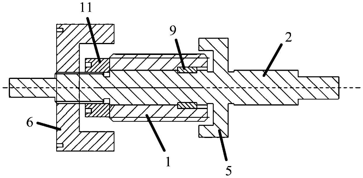
[0054] This embodiment provides an impeller dynamic balance test device, such as Figure 9 shown, which includes:

[0055] mandrel 2;

[0056] In the positioning structure of the mandrel assembly, the impeller is sleeved on the outer surface of the positioning sleeve 1 of the positioning structure of the mandrel assembly, and the first positioning member 5 and the second positioning member 6 are connected to the two ends of the impeller respectively. Such as figure 1 As shown, the positioning structure of the mandrel assembly includes:

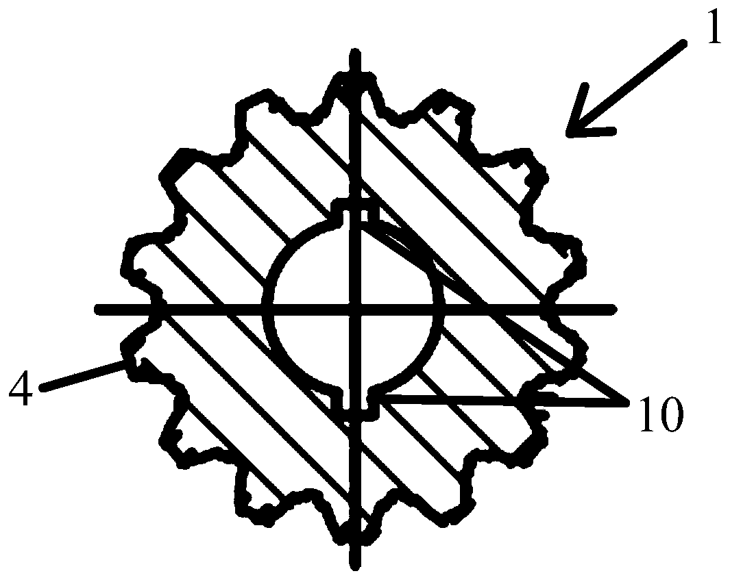
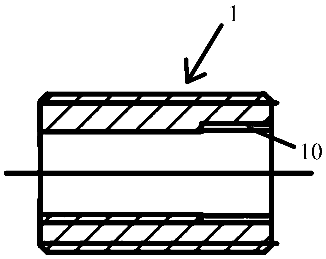
[0057] Locating sleeve 1, such as figure 2 with image 3 As shown, the positioning sleeve 1 is a spline sleeve, and the positioning sleeve 1 and the mandrel 2 are installed together through the flat key 9, and the impeller is installed on the mandrel 2 through the positioning sleeve 1, so that the user can adjust the impeller according to the size of the impeller. By selecting positioning sleeves with different diameters, impellers with ...


PUM


Abstract

The invention discloses a positioning structure for mandrel assembly parts, a use method thereof, and an impeller dynamic balance testing device. The positioning structure for mandrel assembly parts comprises a mandrel, a positioning sleeve arranged on the mandrel in a sleeving mode, and an axial positioning structure, wherein the outer surface of the positioning sleeve is used for sleeving an assembly part to be positioned, and the positioning sleeve is connected with the assembly part through a circumferential positioning structure; and the axial positioning structure comprises a first positioning part and a second positioning part which are positioned in the axial direction of the mandrel and respectively abut against the two ends of the assembly part. By means of the first positioningpart and the second positioning part, the problem that the positioning structure cannot accurately and firmly position the assembly part in the length direction of the mandrel when the positioning sleeve is used for positioning the assembly part in the prior art can be solved.

Description

technical field [0001] The invention relates to the technical field of positioning of components on a mandrel, in particular to a positioning structure and usage method of a mandrel assembly and an impeller dynamic balance test device. Background technique [0002] Assemblies such as impellers need to be installed on the mandrel, and during the process of installing the assemblages on the mandrel, it is necessary to position the assemblages through a positioning structure. For example, the impeller is one of the key components of the turbopump. In the aerospace field, the impeller of the turbopump for liquid rocket engines has high design requirements, and the performance and stability of the impeller directly affect the use of the turbopump. After the impeller is processed, it is necessary to accurately position and install the impeller on the mandrel through the impeller positioning structure, and then perform a dynamic balance test on the impeller to ensure the stability ...

Claims


Application Information

Patent Timeline
Patent Type & Authority Applications(China)
IPC IPC(8): F04D29/20G01M1/02G01M1/14
CPCF04D29/20G01M1/02G01M1/14
Inventor 不公告发明人
Owner BEIJING XINGJI RONGYAO SPACE TECH CO LTD
Learn More