Axial-flow type aeroengine rotor

An aero-engine, axial-flow technology, used in machines/engines, liquid fuel engines, mechanical equipment, etc., can solve problems such as leakage loss, decreased efficiency, and the inability of the sealing device of the rotor blade to play a role in sealing, achieving improved Efficiency, reducing unbalance, increasing overall strength

Active Publication Date: 2019-07-12
AECC COMML AIRCRAFT ENGINE CO LTD
View PDF10 Cites 4 Cited by
  • Summary
  • Abstract
  • Description
  • Claims
  • Application Information

AI Technical Summary

Problems solved by technology

[0004] The technical problem to be solved by the present invention is to provide an axial-flow aero-engine rotor in order to overcome the defects that the sealing device of the rotor blades in the prior art cannot play a sealing role, resulting in air leakage loss and efficiency reduction.

Method used


Image

  • Axial-flow type aeroengine rotor
  • Axial-flow type aeroengine rotor
  • Axial-flow type aeroengine rotor

Examples


Embodiment Construction

[0033] In order to make the above objects, features and advantages of the present invention more comprehensible, specific implementations of the present invention will be described in detail below in conjunction with the accompanying drawings.

[0034] Embodiments of the present invention will now be described in detail with reference to the accompanying drawings. Reference will now be made in detail to the preferred embodiments of the invention, examples of which are illustrated in the accompanying drawings. Wherever possible, the same numbers will be used throughout the drawings to refer to the same or like parts.

[0035] In addition, although the terms used in the present invention are selected from well-known and commonly used terms, some terms mentioned in the description of the present invention may be selected by the applicant according to his or her judgment, and the detailed meanings thereof are set forth herein described in the relevant section of the description. ...


PUM


Abstract

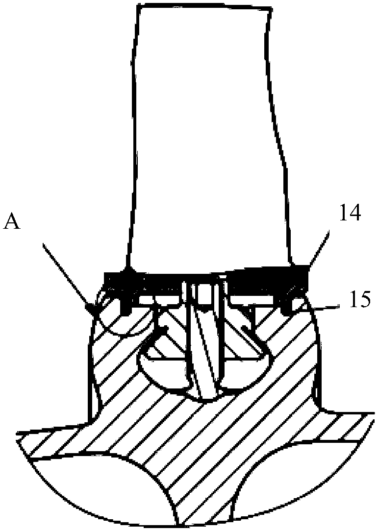
The invention provides an axial-flow type aeroengine rotor. The axial-flow type aeroengine rotor comprises a rotor blade, a locking device and a blade disc, wherein the rotor blade comprises a blade body and a tenon; the tenon is connected with the blade disc, and the rotor blade is circumferentially locked by the locking device; a sawtooth structure is arranged on the lower portion of a margin plate of the blade body of the rotor blade; a first clamping groove is formed in the outer side surface of the sawtooth structure; a first sealing strip is arranged in the first clamping groove; the blade disc is provided with a mounting groove and a tenon groove and the mounting groove and the tenon groove communicate with each other; a convex part is arranged on one side wall of the blade disc; asecond clamping groove is formed in the inner side surface of the convex part; a second sealing strip is arranged in the second clamping groove; the tenon of the rotor blade is arranged in the tenon groove through the mounting groove; and the shape of the outer side surface of the sawtooth structure is matched with the shape of the inner side surface of the convex part, so that the first sealing strip and the second sealing strip are oppositely arranged. According to the axial-flow type aeroengine rotor, the axial sealing effect of the rotor blade and the disc is improved, the leakage loss isreduced, and the margin and the efficiency of a compressor are improved as well.

Description

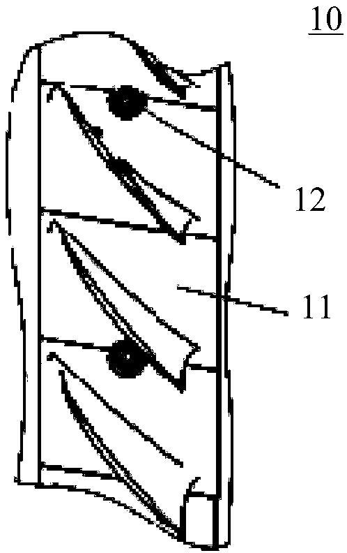
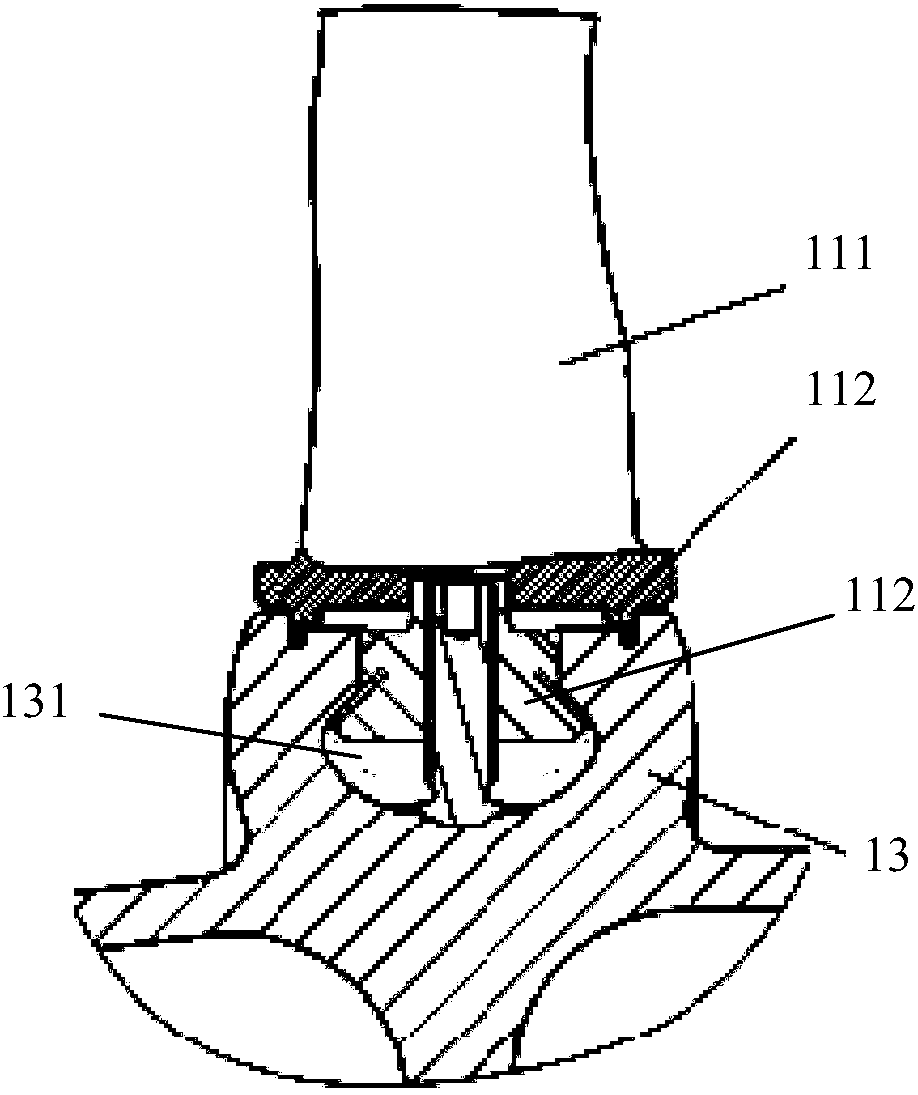
technical field [0001] The invention relates to the field of aero-engine compressors, in particular to an axial-flow aero-engine rotor. Background technique [0002] figure 1 It is a schematic diagram of the rotor structure of an axial-flow aero-engine in the prior art Figure 1 . figure 2 It is a schematic diagram of the rotor structure of an axial-flow aero-engine in the prior art Figure II . Such as figure 1 and figure 2 As shown, in the field of aeroengine compressors, the rotor structure 10 of an axial flow aeroengine is mainly composed of rotor blades 11 , locking devices 12 and discs 13 . The rotor blade 11 is composed of two parts: blade body 111 and tenon 112. The tenon 112 is matched with the tenon groove 131 for installation. The rotor blade 11 is slid and installed in the tenon groove 131 through the installation groove 132 on the disk 13 in sequence, and finally locked by the lock. The tightening device 12 performs circumferential locking on all the ro...

Claims


Application Information

Patent Timeline
Patent Type & Authority Applications(China)
IPC IPC(8): F04D29/32F04D29/08F04D29/34
CPCF04D29/083F04D29/321F04D29/322
Inventor 喻思杨凌元
Owner AECC COMML AIRCRAFT ENGINE CO LTD
Why Eureka
Try Eureka