Multifunctional condensing projection cylinder

A multi-functional and projection technology, applied in the field of photography, can solve the problems of increasing the production cost of the condensing projection tube, inconvenient for high heat generation, and high cost of photography, and achieve the effects of reducing the input cost, simple structure and principle, and simplifying the production process.

Pending Publication Date: 2019-07-12
向茂勇
View PDF0 Cites 0 Cited by
  • Summary
  • Abstract
  • Description
  • Claims
  • Application Information

AI Technical Summary

Problems solved by technology

[0002] At present, the existing concentrating projection tubes mainly include two types of products, one type of projection tube has a convex lens, which can realize focused projection with its own structure, and the other type of projection tube is equipped with a lens interface, so a single-lens reflex lens is used as a convex lens to achieve focused projection , so in order to meet the needs of different occasions, two different types of spotlight projection tubes need to be configured at the same time, so it has the disadvantages of high photography cost and heavy equipment; secondly, the existing spotlight projection tubes use tungsten filament lamps as heating elements The light source belongs to the thermal light source, which is determined to be inconvenient to operate due to high heat generation, and has high requirements for the material and processing technology of the concentrating projection tube, which in turn increases the production cost of the concentrating projection tube

Method used


Image

  • Multifunctional condensing projection cylinder
  • Multifunctional condensing projection cylinder
  • Multifunctional condensing projection cylinder

Examples


Embodiment 1

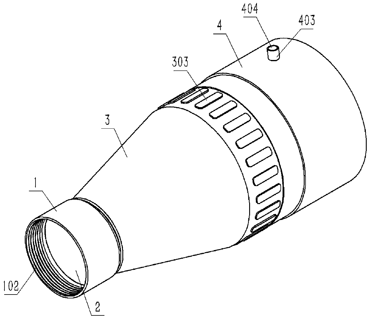
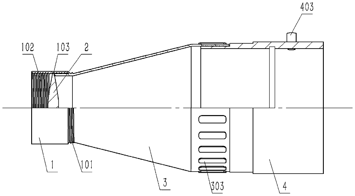
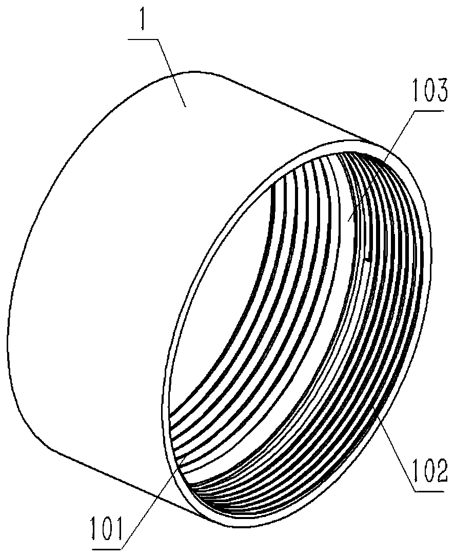
[0036] As attached figure 1 And attached figure 2 As shown, Embodiment 1 includes a fixed ring 1, a convex lens 2, a connecting ring 3, and a focusing ring 4. The entire condensing projection tube is bolted to the flash tube "beam tube". The adjacent rings are connected by threads to avoid any one The shaking of the ring causes the convex lens 2 to shake, and the fine thread 102 facilitates the use of a lens cover to cover the fixing ring 1 to avoid dust. In this embodiment, the second external thread 401 is adjusted to use LED lighting, so that the projection sheet in the annular slot 402 is clearly projected into the photographic scene through the convex lens 2.

Embodiment 2

[0038] As attached Image 6 As shown, Embodiment 2 includes a focusing ring 4 and a conversion ring 5, and the entire condensing projection tube is bolted to the "beam tube" of the flash lamp. This embodiment mainly adjusts the second external thread 401 and adopts LED lighting, so that the projection film in the annular slot 402 is clearly projected into the photography scene through the SLR camera lens. At this time, the focus of the lens is adjusted from the outside. Built-in SLR camera lens.


PUM


Abstract

The invention discloses a multifunctional condensing projection cylinder which comprises a fixed loop, a convex lens, a connecting ring and a focusing ring. The multifunctional condensing projection cylinder has the advantages that the condensing projection cylinder can realize condensing projection via a convex lens and condensing projection via a single-lens reflex lens, two lenses are integrated, and the cost of a photographic condensing projection cylinder is reduced substantially; the condensing projection cylinder is simple in structure and principle, the manufacture cost is reduced greatly, a cold light source is used, a plastic material can be used, problems as heating can be avoided, the production difficulty is reduced greatly, and the production technology is simplified; and thecondensing projection cylinder can be fixed to a small cylinder in the front end of an existing light limiting cylinder in the market, and compared with a condensing projection cylinder of a traditional similar product, the production cost is reduced, the manufacturing difficulty is reduced, and the utilization efficiency of equipment is improved.

Description

Technical field [0001] The present invention relates to the field of photography technology, in particular to a multifunctional light-concentrating projection tube. Background technique [0002] At present, the existing condensing projection tube mainly includes two types of products. One projection tube comes with a convex lens, which can achieve focus projection by using its own structure, and the other projection tube is equipped with a lens interface, so a single-lens reflex lens is used as a convex lens to achieve focus projection. Therefore, in order to meet the needs of different occasions, it is necessary to configure two different types of concentrating projection tubes at the same time, so it has the disadvantages of high photography cost and heavy equipment; secondly, the existing concentrating projection tubes use tungsten filament lamps as heating The light source is a thermal light source, it is determined that it has high heat generation and is inconvenient to oper...

Claims


Application Information

Patent Timeline
IPC IPC(8): G03B13/18
CPCG03B13/18
Inventor 向茂勇
Owner 向茂勇
Why Eureka
Try Eureka