DLP (Digital Light Procession) projection system
A projection system and projection lens technology, applied in optics, instruments, projection devices, etc., can solve the problems of complex structure and high cost, and achieve the effect of simple system structure, low cost, and reduced coherence
- Summary
- Abstract
- Description
- Claims
- Application Information
AI Technical Summary
Problems solved by technology
Method used
Image
Examples
Embodiment 1
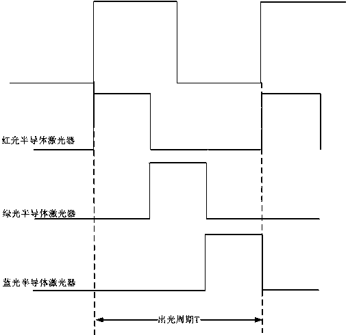
[0053] The driving process of the semiconductor laser provided by the embodiment of the present invention will be described in detail below. Figure 4 A schematic diagram of a driving process of a semiconductor laser provided by an embodiment of the present invention is exemplarily shown. This flow can be implemented in a semiconductor laser drive circuit. see Figure 4 , a semiconductor laser driving process provided by an embodiment of the present invention includes the following steps:
[0054] Step 401, generate a driving signal according to the driving cycle of the semiconductor laser, a driving cycle includes a high-level duration period and a low-level duration period, and the driving signal in the high-level duration period of a driving cycle is composed of N pulses , N is an integer greater than 1; wherein, the peak values of at least two of the N pulses are not equal, and / or, at least two of the N-1 pulse intervals formed by the N pulses The intervals are not eq...
Embodiment 2
[0061] The implementation process of the second embodiment is basically the same as that of the first embodiment. In particular, when the peak values of at least two pulses among the N pulses generated in step 401 are not equal, the N-1 pulse intervals formed by the N pulses can be equal.
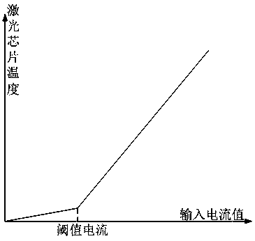
[0062] In the second embodiment, the operating temperature of the semiconductor laser chip can generally be changed as long as the peak values of at least two pulses among the N pulses in the high level duration period of a driving cycle are not equal. In order to effectively control the operating temperature of the semiconductor laser chip and increase the wavelength of the semiconductor laser output light, in the preferred solution provided by the embodiment of the present invention, the pulse peak value of N pulses in the high level duration period of one driving cycle of the semiconductor laser The changing rules of may include any one of the following rules a1 to a3.
[0063] Rule...
Embodiment 3
[0083] The implementation process of the third embodiment is basically the same as that of the first embodiment. In particular, when the N-1 pulse intervals formed by the N pulses produced in step 401 are not equal, the peak values of the N pulses may be equal.
[0084] In Embodiment 3, when at least two of the N-1 pulse intervals formed by N pulses in the high-level duration period of one driving cycle of the semiconductor laser have unequal pulse intervals, the N-1 pulse intervals formed by N pulses The change rules of pulse intervals may include any one of the following rules b1 to b3:
[0085] Rule b1, N-1 pulse intervals formed by N pulses during the high-level duration period of one driving cycle of the semiconductor laser are incremented.
[0086] Further, the N-1 pulse intervals formed by the N pulses in the high-level period of the semiconductor laser can be linearly increasing, or nonlinearly increasing, for example, increasing according to the increasing part of t...
PUM
 Abstract
Description
Claims
Application Information
 - R&D
- Intellectual Property
- Life Sciences
- Materials
- Tech Scout
- Unparalleled Data Quality
- Higher Quality Content
- 60% Fewer Hallucinations
Browse by: Latest US Patents, China's latest patents, Technical Efficacy Thesaurus, Application Domain, Technology Topic, Popular Technical Reports.
© 2025 PatSnap. All rights reserved.Legal|Privacy policy|Modern Slavery Act Transparency Statement|Sitemap|About US| Contact US: help@patsnap.com


