
Connection structure and electronic equipment

A technology of connection structure and transmission structure, applied in the field of electronics, can solve problems such as limiting the miniaturization of gear shafts, failing to meet the development needs of enterprises, and limiting the use scenarios of gear shafts

Pending Publication Date: 2019-07-12
LENOVO (BEIJING) CO LTD
View PDF8 Cites 0 Cited by
  • Summary
  • Abstract
  • Description
  • Claims
  • Application Information

AI Technical Summary

Problems solved by technology

However, the series of measures adopted limit the miniaturization of the gear shaft, thereby limiting the use scenarios of the gear shaft, which brings a lot of inconvenience to users. At the same time, this series of measures also increases the development and production costs of the enterprise. , can not meet the development needs of enterprises

Method used


Image

  • Connection structure and electronic equipment
  • Connection structure and electronic equipment
  • Connection structure and electronic equipment

Examples


Embodiment Construction

[0037] The technical solution of the present application will be further described in detail below in conjunction with the accompanying drawings and specific embodiments. It should be noted that the shapes and sizes of the structures in the drawings are only schematically illustrating the embodiments of the present application, and are not intended to limit the structures.

[0038] In order to better understand the embodiments of the present application, firstly, the commonly used connection structures in related technologies will be described.

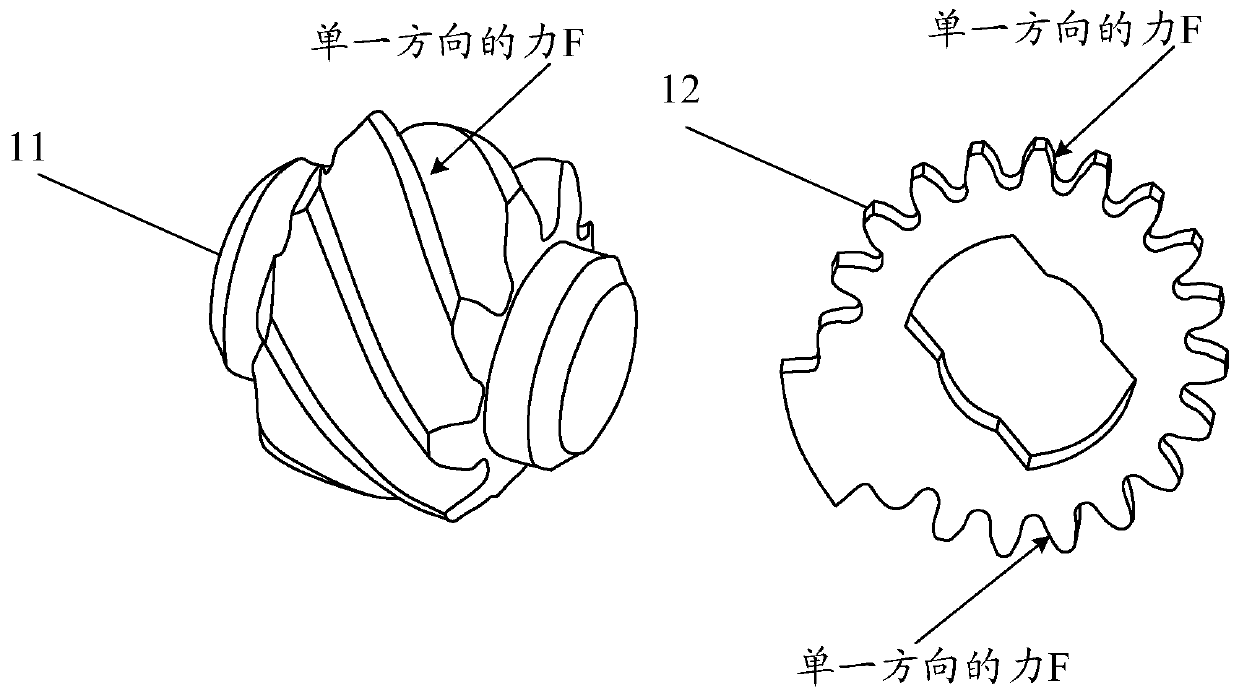
[0039] Traditional gears, especially the pinion gears in the middle, are under single-sided force. As the gears and teeth of thin and light models are getting smaller and smaller, the strength is greatly challenged. figure 1 It is a schematic diagram of the composition and structure of gears used for transmission in the related art, such as figure 1 As shown, the transmission device in the related art is generally divided into a shaf...


PUM


Abstract

The embodiment of the invention discloses a connecting structure and electronic equipment, and the connecting structure comprises a first rotating device which comprises a first gear located at the first end of the first rotating device; the second rotating device which comprises a second gear located at the first end of the second rotating device; and a transmission device which is meshed with the first gear and the second gear at the same time, so that the rotation of the first rotating device can be transmitted to the second rotating device.

Description

technical field [0001] The embodiment of the present application relates to electronic technology, and relates to but not limited to a connection structure and electronic equipment. Background technique [0002] The gear shaft is a commonly used and important transmission element, which is widely used in various equipment. In the current practical application, the gear of the gear shaft has the threat of fatigue fracture. Generally, a series of measures are taken, such as changing the material of the gear, increasing the thickness of the gear, and reducing the number of teeth of the gear to improve or eliminate the fatigue fracture of the gear. threat. However, the series of measures adopted limit the miniaturization of the gear shaft, thereby limiting the use scenarios of the gear shaft, which brings a lot of inconvenience to users. At the same time, this series of measures also increases the development and production costs of the enterprise. , can not meet the developme...

Claims


Application Information

Patent Timeline
IPC IPC(8): G06F1/16
CPCG06F1/1656G06F1/1675
Inventor 罗军超
Owner LENOVO (BEIJING) CO LTD
Features
  • Generate Ideas
  • Intellectual Property
  • Life Sciences
  • Materials
  • Tech Scout
  • Unparalleled Data Quality
  • Higher Quality Content
  • 60% Fewer Hallucinations
Learn More