Fuel cell system

一种燃料电池系统、燃料电池的技术,应用在燃料电池、动力系统燃料电池、电路等方向,能够解决难水分排出等问题

Active Publication Date: 2019-07-12
TOYOTA JIDOSHA KK
View PDF10 Cites 2 Cited by
  • Summary
  • Abstract
  • Description
  • Claims
  • Application Information

AI Technical Summary

Problems solved by technology

[0007] However, in the prior art described in the aforementioned Patent Document 1 and the like, it is necessary to stop the operation of the fuel cell in order to perform the purge treatment, and it is difficult to discharge moisture (ice) temporarily frozen in a low-temperature environment to the outside.

Method used


Image

  • Fuel cell system
  • Fuel cell system
  • Fuel cell system

Examples


Embodiment Construction

[0022] Hereinafter, the structure of this invention is demonstrated in detail based on an example of embodiment shown in drawing. Hereinafter, as an example, a case where the present invention is applied to a fuel cell mounted on a fuel cell vehicle or a fuel cell system including the same will be described, but the scope of application is not limited to such an example.

[0023] [System configuration of fuel cell system]

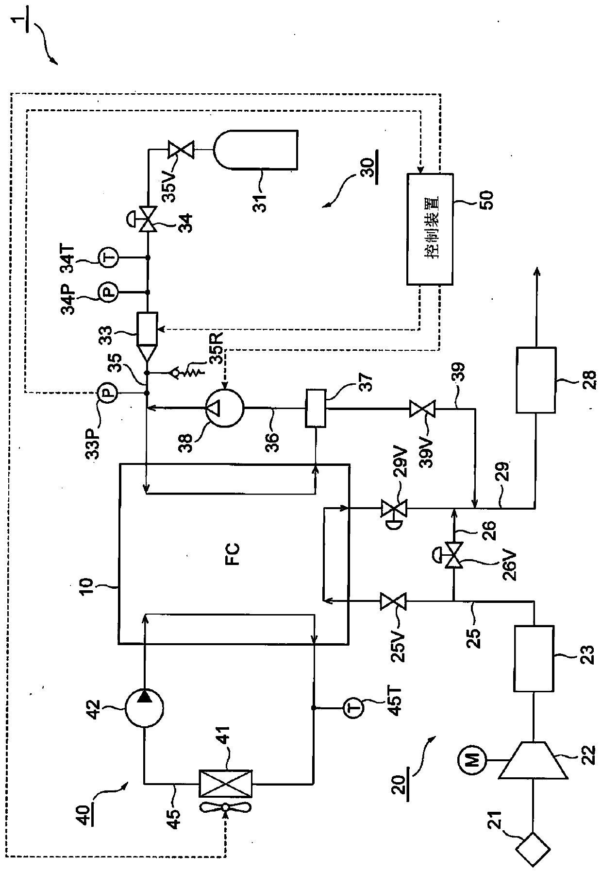
[0024] First, use figure 1 A system configuration of a fuel cell system including a fuel cell according to the present invention will be schematically described.

[0025] figure 1 The illustrated fuel cell system 1 includes, for example: a fuel cell (fuel cell stack) 10 configured by stacking a plurality of fuel cells serving as unit cells; an oxidizing gas supply system 20 for supplying an oxidizing gas such as air to the fuel cell 10; A fuel gas supply system 30 that supplies fuel gas such as hydrogen to the fuel cell 10; a refrigerant supply system 40...


PUM


Abstract

Provided is a fuel cell system that can effectively suppress clogging of a pipe due to freezing of water in a fuel gas supply system thereof without the need for halting the operation of the fuel cells, and thus is highly reliable. When possible freezing of water is detected or presumed to be present downstream of an injector (33), the amount of a fuel gas to be supplied from a circulation pump (38) that is disposed in a circulation channel (36) is relatively increased compared to the amount of the fuel gas to be supplied from the injector (33).

Description

technical field [0001] The present invention relates to fuel cell systems. Background technique [0002] Conventionally, a fuel cell system including a fuel cell (fuel cell stack) that generates electricity by an electrochemical reaction between an oxidizing gas such as air and a reaction gas of a fuel gas such as hydrogen is known. [0003] In the fuel cell system described above, water is generated during power generation, and if the water remains in the fuel cell even after power generation is stopped, it freezes when the outside air temperature drops, for example, resulting in lowered efficiency when power generation starts next time. [0004] For example, a fuel gas supply system that supplies fuel gas such as hydrogen to a fuel cell includes a fuel gas supply source (hydrogen tank) that stores high-pressure fuel gas, and supplies the fuel gas from the fuel gas supply source to the fuel cell. The fuel gas supply flow path (piping), the circulation flow path for returni...

Claims


Application Information

Patent Timeline
Patent Type & Authority Applications(China)
IPC IPC(8): H01M8/04746
CPCH01M8/04753H01M8/04253H01M8/04664H01M8/04302H01M8/04388H01M2250/20H01M8/04723Y02T90/40Y02E60/50H01M8/04671H01M8/04955
Inventor 田中诚一户井田政史常川洋之松本峻丸尾刚
Owner TOYOTA JIDOSHA KK
Why Eureka
Try Eureka