
Wire-rotatable suspension clamp

A technology for suspending wire clips and wires, which is applied to the suspension device of cables, installation of cables, electrical components, etc., can solve the problem that wires are not paid enough attention, achieve good rotation effect, restrain galloping, and weaken eccentric icing. Effect

Pending Publication Date: 2019-07-12
NORTH CHINA ELECTRICAL POWER RES INST +3
View PDF0 Cites 1 Cited by
  • Summary
  • Abstract
  • Description
  • Claims
  • Application Information

AI Technical Summary

Problems solved by technology

The components on the line that are directly connected to the conductor and limit the rotation of the conductor include spacer bars and suspension clamps. The spacer bars are used on the wires between the iron towers. Generally, a spacer bar is installed every tens of meters to support the sub-conductors of the split wires. , due to the high installation density of the spacer rods, the influence on the rotation, icing and galloping of the conductors is paid attention to; the suspension clamp is only used on each base iron tower (straight-line tower), clamping the conductor and suspending the conductor on the tower, That is, the installation interval of the suspension clamp is the distance between the two base iron towers, generally 300m-500m. Although the wires clamped in the suspension clamp are completely fixed, the installation density of the suspension clamp is much smaller than that of the spacer. Therefore, its influence on the rotation, icing and galloping of the wire has not been paid enough attention

Method used


Image

  • Wire-rotatable suspension clamp
  • Wire-rotatable suspension clamp
  • Wire-rotatable suspension clamp

Examples


Embodiment Construction

[0051] The following will clearly and completely describe the technical solutions in the embodiments of the present invention with reference to the accompanying drawings in the embodiments of the present invention. Obviously, the described embodiments are only some, not all, embodiments of the present invention. Based on the embodiments of the present invention, all other embodiments obtained by persons of ordinary skill in the art without making creative efforts belong to the protection scope of the present invention.

[0052] As used herein, "first", "second", ..., etc. do not refer to the meaning of sequence or order, nor are they used to limit the present invention. They are only used to distinguish elements or components described with the same technical terms. operate.

[0053] As used herein, "comprising", "comprising", "having", "comprising" and so on are all open terms, meaning including but not limited to.

[0054] As used herein, "and / or" includes any or all combin...


PUM


Abstract

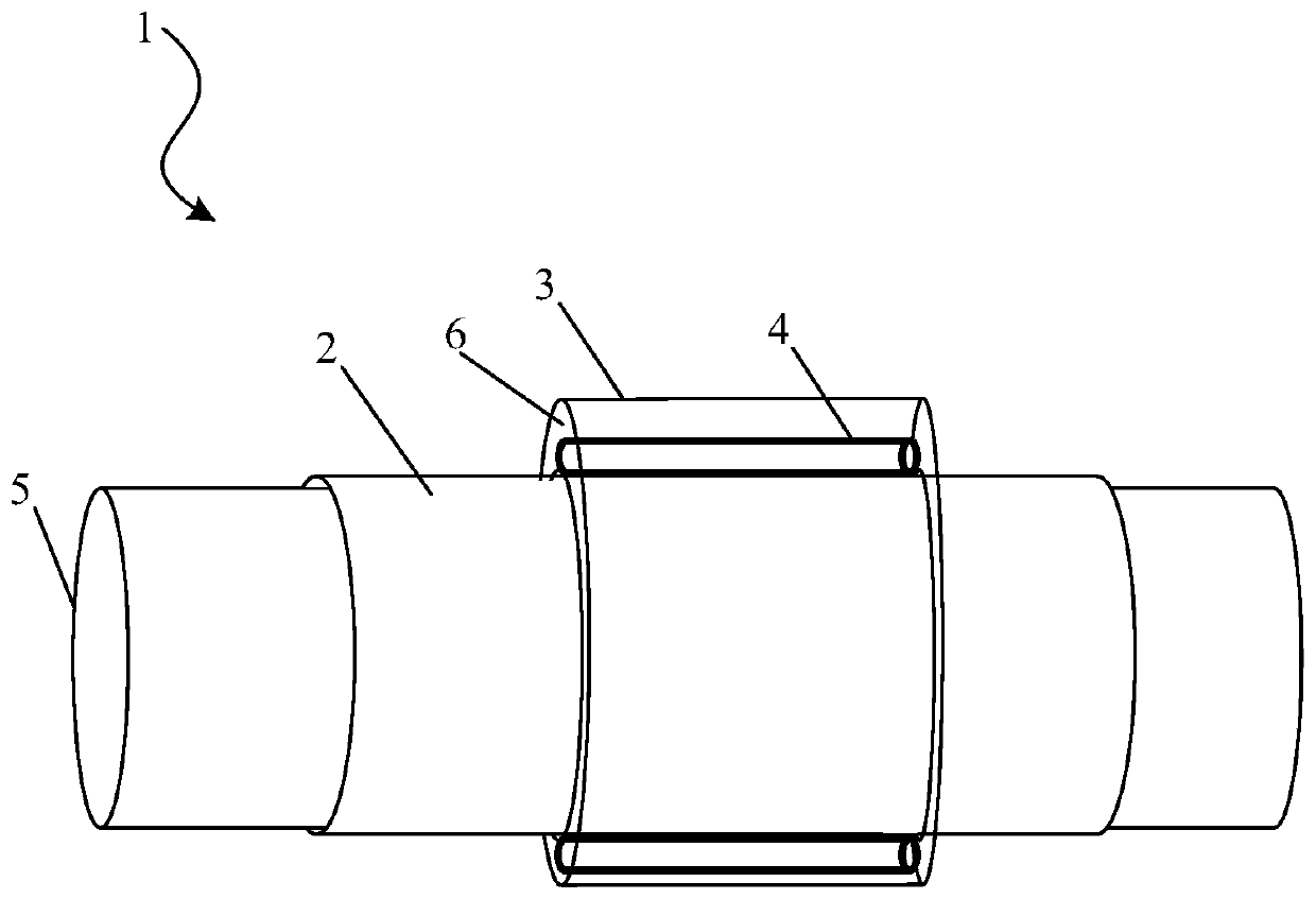
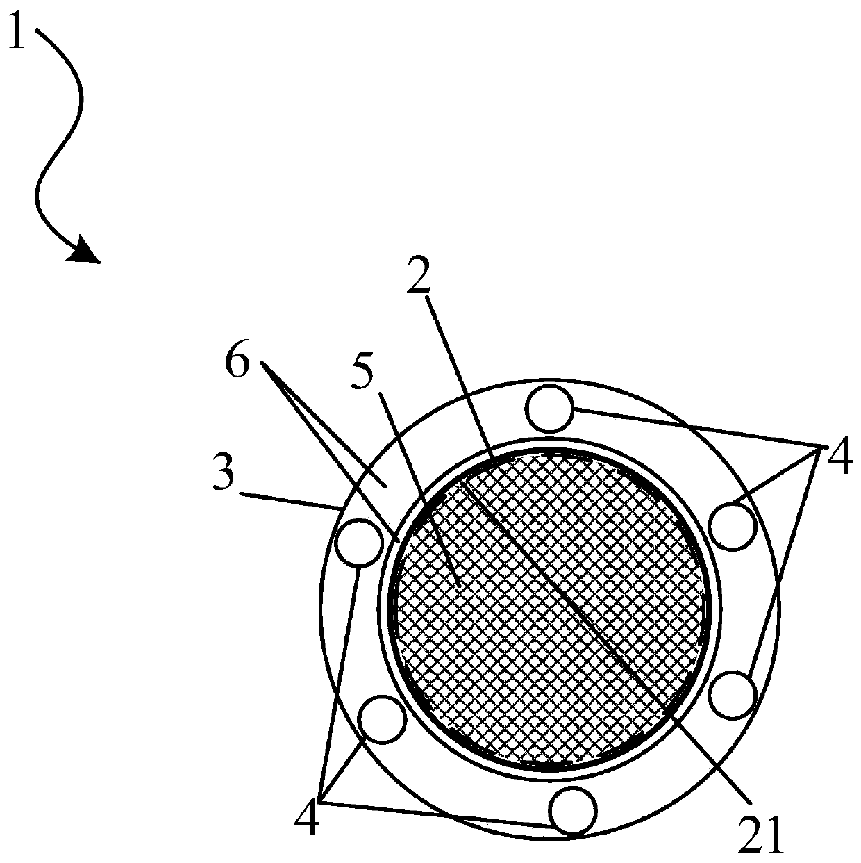
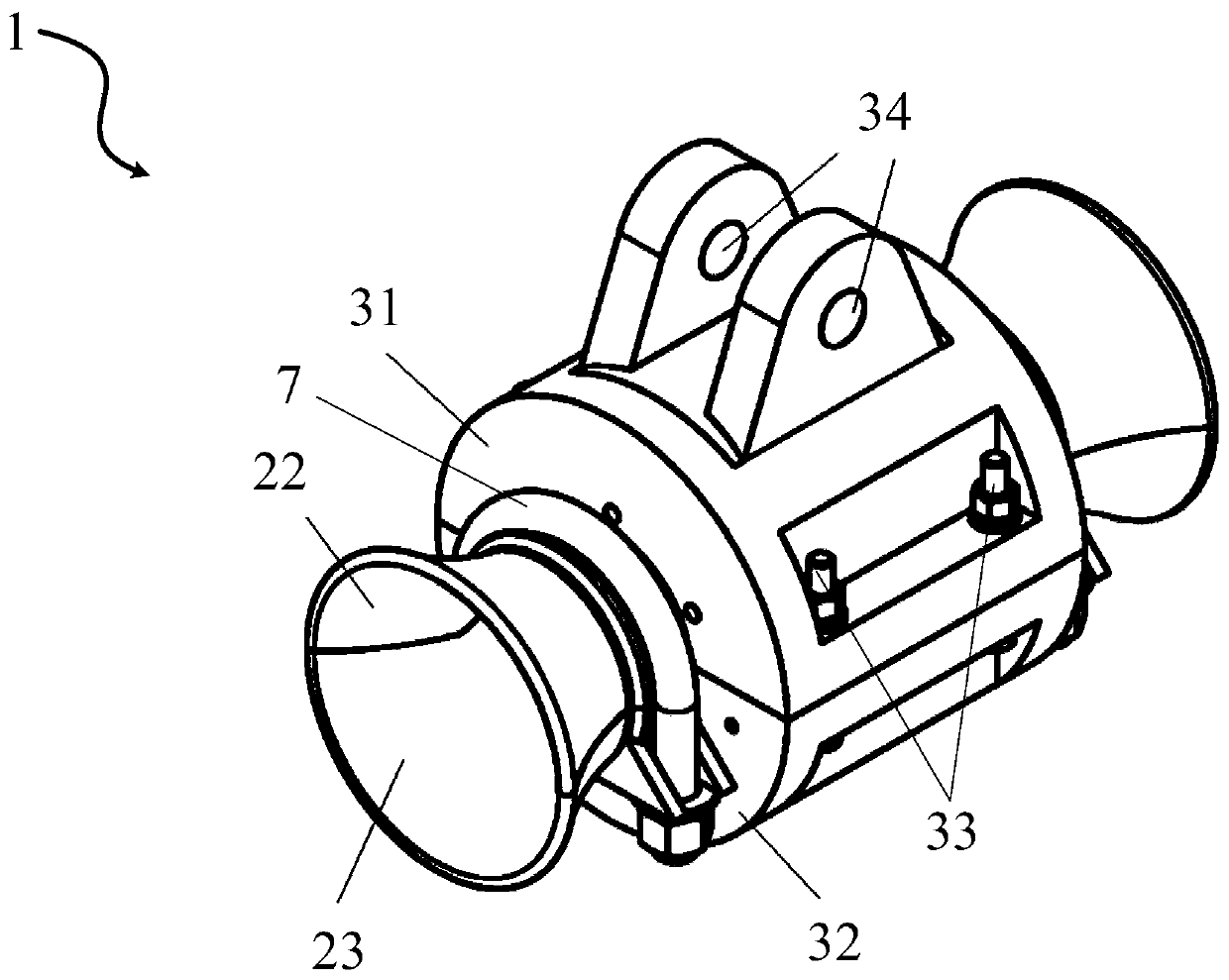
The present invention provides a wire-rotatable suspension clamp, comprising an inner casing for clamping a wire, an outer casing, and a rotating portion disposed between the inner casing and the outer casing; the inner casing penetrates through the chamber of the of the outer casing; an annular gap is formed between the inner casing and the outer casing; the inner casing is not in contact with the outer casing; the axial central line of the inner casing coincides with the axial central line of the outer casing; and the rotating portion is disposed in the annular gap and rotates relative to the inner casing. By means of the rotating portion, the wire clamped by the suspension clamp has a good rotation effect, and the suspension clamp has the advantages of weakening the eccentric ice formedon the wire under rain, snow and freezing weather conditions, suppressing the vibration of the wire, and improving the safe operation level of the line and the power grid.

Description

technical field [0001] The invention relates to the technical field of electric power transmission, in particular to a wire rotatable suspension clamp for preventing the wire galloping of an overhead power transmission line. Background technique [0002] Overhead transmission lines (referred to as lines) are important equipment for transmitting electric energy. They are composed of line towers, wires, overhead ground wires and other components. The wires of the AC line include A, B, and C phases, and the wires of the DC line include positive and negative poles. . Under certain icing and strong wind conditions, uneven eccentric icing can be formed on the conductor, which changes the aerodynamic performance of the conductor and easily causes large-scale vibration of the conductor, which is vividly called galloping. Galloping can reduce the distance between conductors and cause discharge tripping; it can also increase the tension of conductors and cause tower collapse and disc...

Claims


Application Information

Patent Timeline
Patent Type & Authority Applications(China)
IPC IPC(8): H02G7/05H02G7/14
CPCH02G7/053H02G7/14
Inventor 陈原王得文
Owner NORTH CHINA ELECTRICAL POWER RES INST
Learn More