Pushing and discharging method for unloading hole of automatic grinding machine

An automatic grinding machine and material port technology, which is applied in the direction of grinding machine parts, grinding/polishing equipment, metal processing equipment, etc.

CN110014366AInactive Publication Date: 2019-07-16ZHUJI TIANYA TECH CO LTD
0 Cites 0 Cited by

Patent Information

Authority / Receiving Office
CN · China
Patent Type
Applications(China)
Current Assignee / Owner
Publication Date
2019-07-16
Estimated Expiration
Not applicable · inactive patent

Smart Images

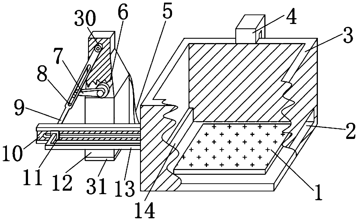
  • Figure 1
    Figure 1
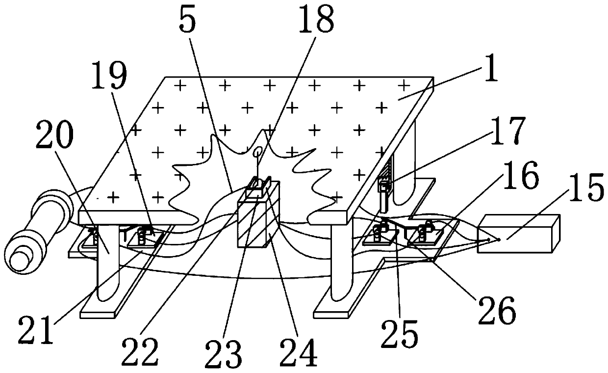
  • Figure 2
    Figure 2
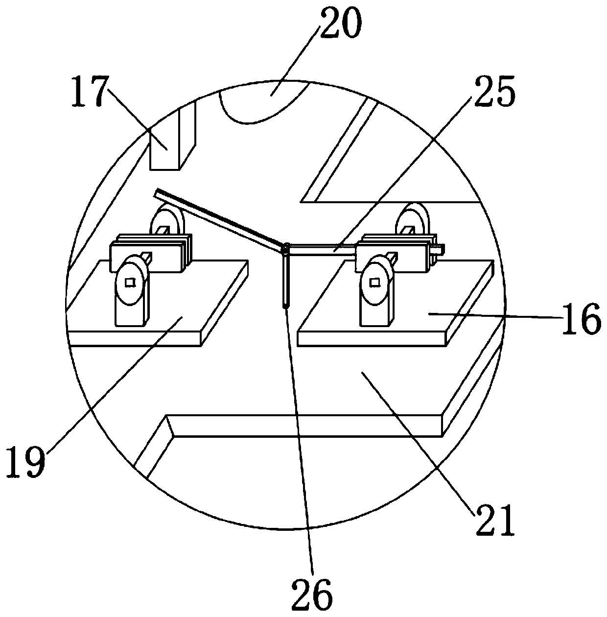
  • Figure 3
    Figure 3
Patent Text Reader

Abstract

The invention discloses a pushing and discharging device for an unloading hole of an automatic grinding machine. The pushing and discharging device comprises a receiving box and a motor box, wherein the left end of the receiving box is equipped with the motor box; the left side of the lower end of the inner cavity of the receiving box is equipped with a pushing plate; the four corners of the lowerend of a movable plate are fixedly connected with springs, and two switches of a circuit are connected in parallel; and an electromagnet is electrically connected to two first switches and a power supply through guide wires; two first switches of the circuit are connected in series. According to the pushing and discharging device for the unloading hole of the automatic grinding machine disclosedby the invention, the power supply, the guide wires, the two first switches and a double-pole switch are electrically connected to the electromagnet, and the two first switches are connected in series, so that when any mechanism is triggered, the electromagnet is powered off; and the power supply, the guide wires, the two second switches and the double-pole switch are electrically connected to a motor, and the two second switches are in connected in parallel, so that the motor is powered on to control return and discharge purpose through the triggered mechanism so as to reach the expected effect of a client when any mechanism is triggered.
Need to check novelty before this filing date? Find Prior Art

Description

Technical field

[0001] The invention relates to the technical field of grinders, in particular to an automatic grinder discharging port pushing and discharging device. Background technique

[0002] The grinder is a machine tool that uses abrasive tools to grind the surface of the workpiece. Most of the grinders use high-speed rotating grinding wheels for grinding, usually pushing and discharging at the discharge port, such as 2012220564463.7, with a V-shaped channel, V A vertical material channel is installed above the material channel. One end of the V material channel is equipped with a cylinder. The piston rod of the cylinder is fixedly connected with a pushing block, which faces the exit position of the material channel, although it can solve the problem of cutting The push movement at the mouth, but it cannot automatically trigger the push and push of the feeding mouth, which cannot meet the requirements of customers. Summary of the invention

[0003] The purpose of the pres...

Examples

Embodiment Construction

[0021] The technical solutions in the embodiments of the present invention will be clearly and completely described below in conjunction with the accompanying drawings in the embodiments of the present invention. Obviously, the described embodiments are only a part of the embodiments of the present invention, rather than all the embodiments. Based on the embodiments of the present invention, all other embodiments obtained by those of ordinary skill in the art without creative work shall fall within the protection scope of the present invention.

[0022] See Figure 1-5 , The present invention provides a technical solution: an automatic grinder discharging port pushing and discharging device, comprising a receiving box 3 and a motor box 12. The left end of the receiving box 3 is provided with a motor box 12, and the bottoms of the two devices are on the same plane. On the lower end of the right side of the receiving box 3 is provided with a discharge port 2. The discharge port 2 c...