Oil distribution tank for replacing air conditioner refrigerant and system applying oil distribution tank

A refrigerant and oil tank technology, applied in the system field, can solve the problems of refrigerant waste, unfavorable refrigerant environment, physical health damage, etc., and achieve the effects of eliminating leakage and waste, maintaining working environment, and simple structure design.

Pending Publication Date: 2019-07-16
SOUTH AIR INT
View PDF0 Cites 0 Cited by
  • Summary
  • Abstract
  • Description
  • Claims
  • Application Information

AI Technical Summary

Problems solved by technology

[0007] Refrigerant is always unfavorable to the environment, especially in a small space like a laboratory, once people inhale it, their health will cause immeasurable damage;
[0008] It causes waste of refrigerant and increases the development cost. The amount of refrigerant released at one time reaches more than 500g, and the loss at one time is about 500 yuan;
[0009] The method of releasing refrigerant with natural leakage cannot guarantee the quantification of the oil output, nor can it completely prevent the refrigerant oil from going out;
[0010] The refrigerant release method with natural leakage takes more than 30 minutes, and a test only takes 2 hours. Such an intermediate waiting time reduces the overall efficiency

Method used


Image

  • Oil distribution tank for replacing air conditioner refrigerant and system applying oil distribution tank
  • Oil distribution tank for replacing air conditioner refrigerant and system applying oil distribution tank
  • Oil distribution tank for replacing air conditioner refrigerant and system applying oil distribution tank

Examples


Embodiment 1

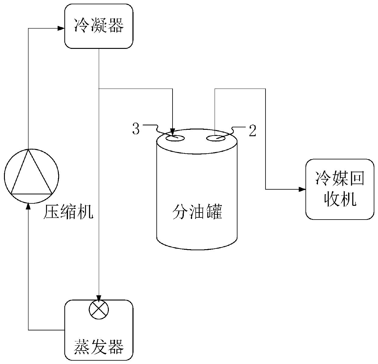
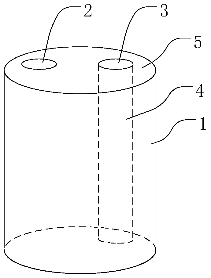
[0036] The invention relates to an oil separation tank for replacing air-conditioning refrigerant, comprising a tank body 1, a refrigerant outlet 2 arranged on the top of the tank body 1, and a refrigerant inlet 3 arranged on the tank body 1; 1 communicates with a conduit 4 leading into the bottom of the tank body 1 . The refrigerant inlet 3 is arranged on the top of the tank body 1 on the same side as the refrigerant outlet 2 , and the conduit 4 is a straight pipe connecting the refrigerant inlet 3 to the bottom of the tank body 1 .

[0037] Optionally, the tank body 1 is made of a transparent material, so that the recovery ratio of the refrigerated oil can be checked at any time, and the refrigerated oil can be poured back into the system before the refrigerated oil is full. Both the refrigerant inlet 3 and the refrigerant outlet 2 are provided with sealing gaskets to prevent the refrigerant from leaking at the refrigerant inlet 3 and the refrigerant outlet 2 . The side of ...

Embodiment 2

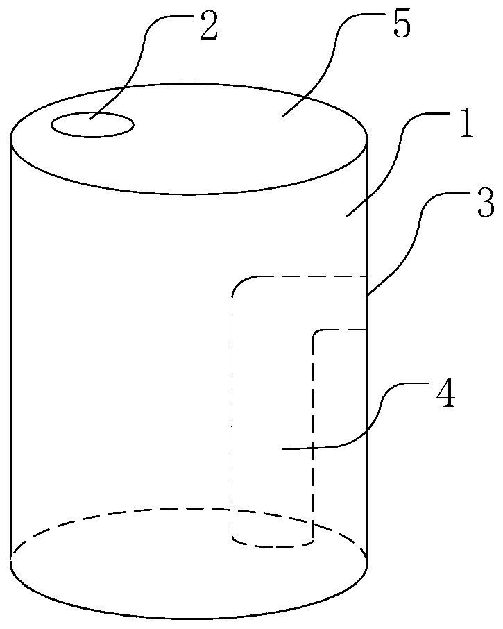
[0041] The difference between this embodiment and the first embodiment is that the refrigerant inlet 3 in this embodiment is arranged on the side wall of the tank body 1 , and the conduit 4 is an elbow connecting the refrigerant inlet 3 to the bottom of the tank body 1 .

Embodiment 3

[0043] The difference between this embodiment and the second embodiment is that the conduit 4 in this embodiment is a straight pipe arranged obliquely, connecting the refrigerant inlet 3 to the bottom of the tank body 1

[0044] The invention eliminates the leakage and waste of the refrigerant through the simple structure design of the oil separation tank, maintains a healthy working environment, and reduces the environmental pollution caused by the leakage of the refrigerant; the cost of the refrigerant is reduced by at least 10,000 yuan per year; It takes half an hour for natural leakage, and the recovery time is 5-8 minutes by using the oil separation tank, which improves the efficiency by at least 80%.


PUM


Abstract

The invention belongs to the field of air conditioners and relates to an oil distribution tank for replacing air conditioner refrigerant and a system applying the oil distribution tank. The oil distribution tank comprises a tank body, a refrigerant outlet arranged at the top of the tank body and a refrigerant inlet arranged on the tank body. A guide pipe led into the bottom of the tank body communicates with the refrigerant inlet in the tank body. The system comprises the oil distribution tank, a refrigerant recovery machine and a condenser, the refrigerant inlet of the oil distribution tank is connected with the condenser and used for collecting refrigerant flowing out of the condenser, after the refrigerant flows into the oil distribution tank, refrigerating oil of a compressor is remained at the bottom of the oil distribution tank, and the refrigerant outlet of the oil distribution tank is connected with the refrigerant recovery machine. Leakage waste of the refrigerant is completely avoided, the healthy working environment is maintained, and environmental pollution caused by the leakage of the refrigerant is also reduced; the refrigerant cost is reduced by at least 10,000 yuanor more each year; natural leakage of the refrigerant takes half an hour, the oil distribution tank is used for recovering the refrigerant for 5-8 minutes, and the efficiency is improved by 80%.

Description

technical field [0001] The invention belongs to the field of air conditioners, and relates to an oil separation tank for replacing air-conditioning refrigerants and a system using the oil separation tank. Background technique [0002] The current air-conditioning industry, whether it is household, commercial or automotive air-conditioning, will involve a large number of development tests, among which charging refrigerant (R22, R134a, R410a, etc.) for performance testing accounts for an important part of the development test. [0003] Generally, the objects to be tested are the key components of refrigeration (compressors, condensers and evaporators); when testing the performance of components (such as power consumption, performance and other parameters), they must first be connected into a closed system. The system must include a compressor that can do work, a condensing unit that can condense, and an evaporation unit that can refrigerate; after the refrigerant is charged in...

Claims


Application Information

Patent Timeline
IPC IPC(8): F25B43/02F25B45/00
CPCF25B43/02F25B45/00
Inventor 李广杜伟张继鑫廖新耀
Owner SOUTH AIR INT
Why Eureka
Try Eureka