Side channel compressor having a seal assembly

A technology of sealing components and side channels, which is applied to the sealing of engines, pump components, mechanical equipment, etc., can solve the problems of reduced efficiency level, wear of sealing components, satisfactory sealing effect of sealing components, etc., and achieve the effect of reliable function

Active Publication Date: 2019-07-16
GARDNER DENVER DEUTLAND
View PDF6 Cites 0 Cited by
  • Summary
  • Abstract
  • Description
  • Claims
  • Application Information

AI Technical Summary

Problems solved by technology

On the downside, seal assemblies are often subject to wear over the life of the side channel compressor, resu...

Method used


Image

  • Side channel compressor having a seal assembly
  • Side channel compressor having a seal assembly
  • Side channel compressor having a seal assembly

Examples


Embodiment Construction

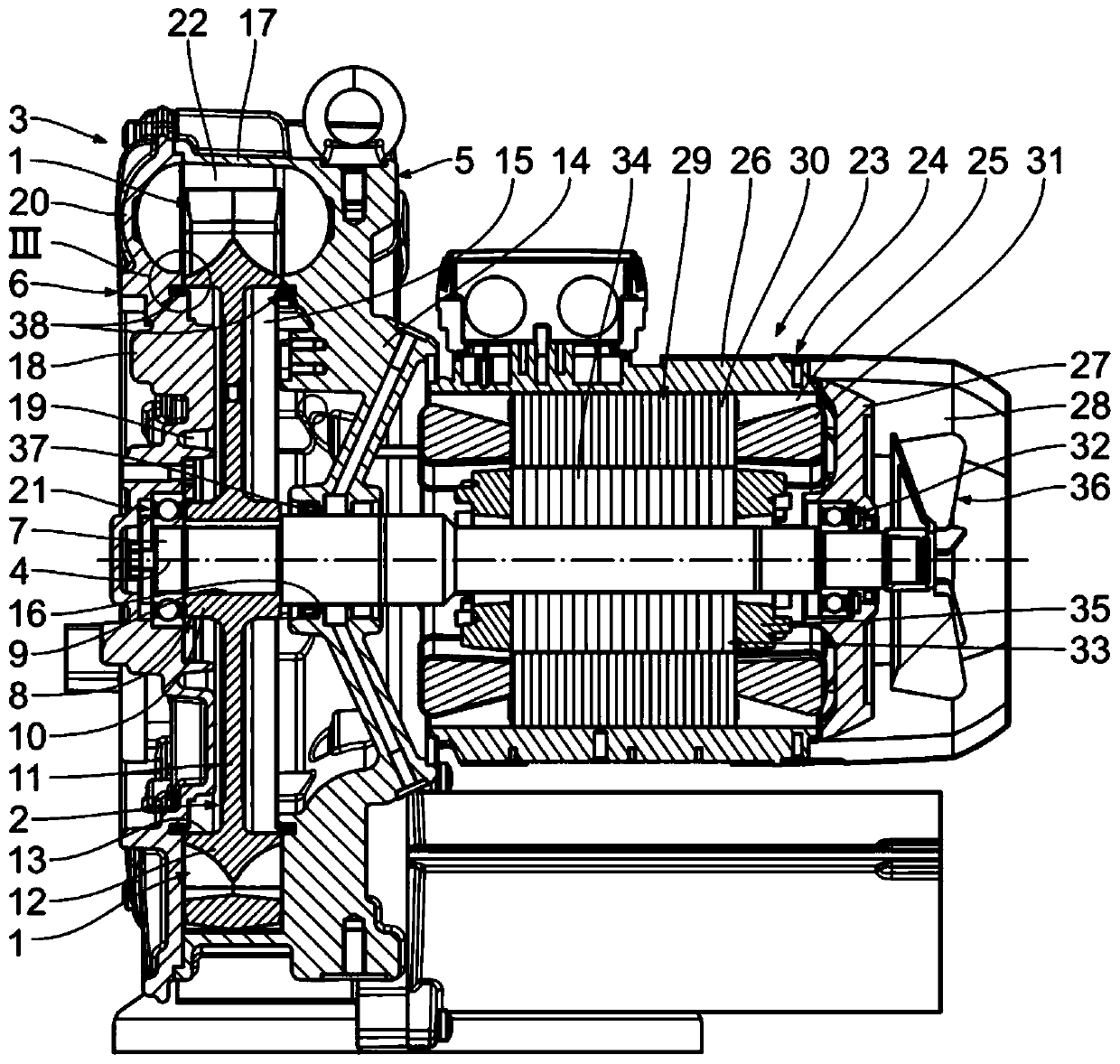
[0038] First, refer to figure 1 ,exist figure 1 shows generally an assembled side channel compressor for compressing a gas, comprising an impeller 2 provided with impeller blades 1 and mounted so that it can be positioned sideways about a longitudinal central axis 4 The rotary drive is carried out in the casing 3 of the channel compressor. Thus, the longitudinal center axis 4 forms an axis of rotation.

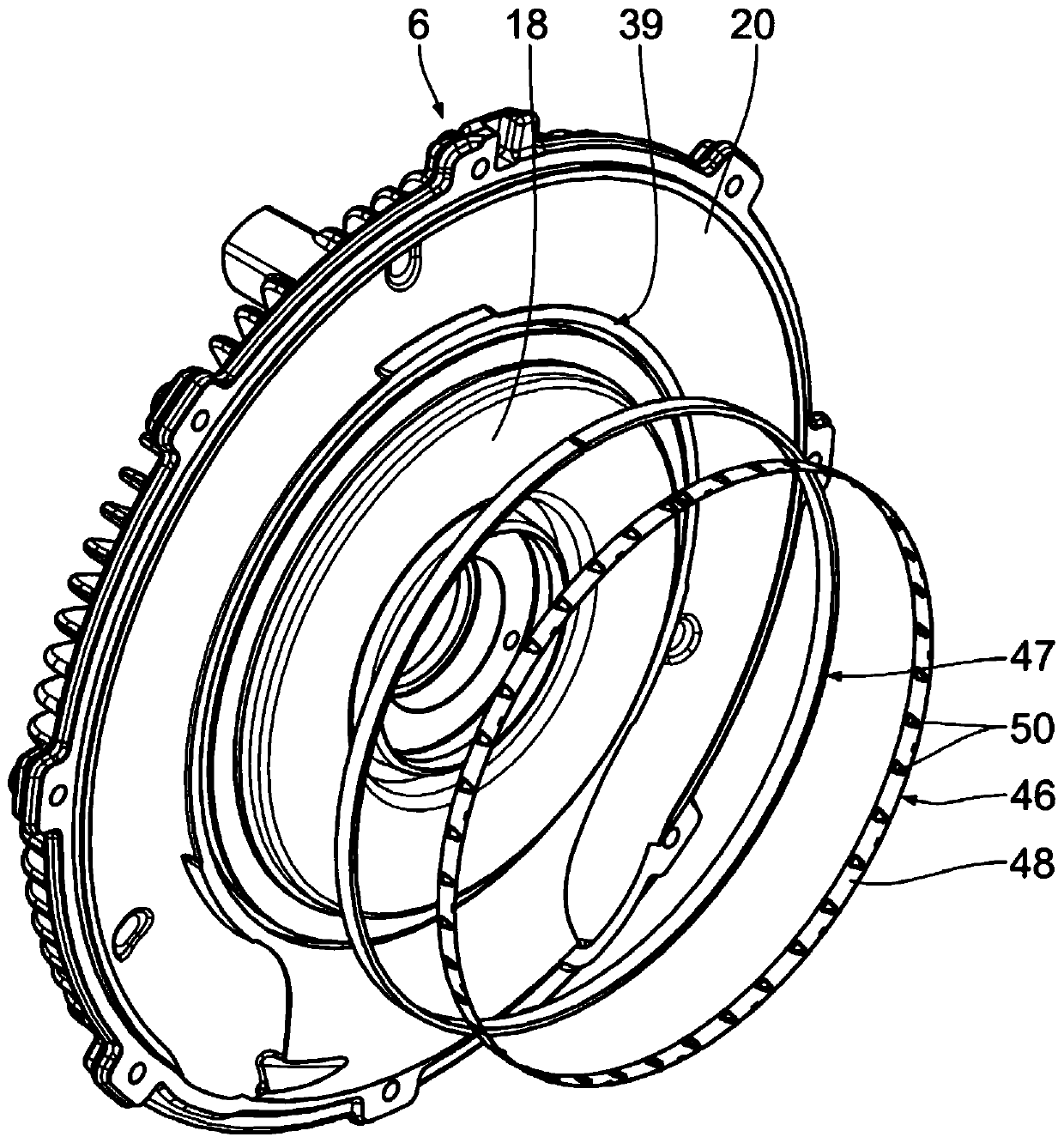
[0039] The case 3 has a housing 5 and a removable case cover 6, according to figure 1 , the casing 5 and the removable casing cover 6 are aligned together and together surround the impeller 2 , which is arranged in a rotationally fixed manner on the drive shaft 7 and has the impeller blades 1 .

[0040] The single-row impeller 2 is configured in the manner of a disk. The single-row impeller 2 has an impeller hub 8 with a central hub bore 9 . The impeller hub 8 is formed by an inner hub foot 10 adjoining the hub bore 9 radially outwards and an annular hub 11 adjoining said...


PUM


Abstract

The invention relates to a side channel compressor for sealing a gas, comprising a housing (3) and at least one impeller (2), which is arranged in the housing and can be rotationally driven about a central axis (4). The side channel compressor further comprises at least one seal assembly (38) arranged in the housing (3) having at least one sealing device (47), which seals at least one gap (59) between the housing (3) and the at least one impeller (2) and forces the same radially outwards with respect to the central axis (4) in order to keep the at least one gap (59) small. The at least one seal assembly (38) further comprises at least one sealing device holding unit (46), which axially fixes the at least one sealing device (47) in place with respect to the central axis (4) and is providedwith at least one holding main body (48).

Description

technical field [0001] The present invention relates to a side channel compressor for compressing gases such as air or industrial gases. The side-channel compressor is embodied, for example, as a side-channel fan. Background technique [0002] Side channel compressors are well known from the prior art. The level of efficiency of a side channel compressor depends on the leakage flow that occurs. In order to avoid such leakage flows, corresponding sealing assemblies are used. Unfortunately, seal assemblies are often subject to wear over the life of the side channel compressor, resulting in reduced efficiency levels. In addition, the sealing effect of the sealing assembly is not always satisfactory. Contents of the invention [0003] This patent application claims priority from German patent application DE 10 2016 222 430.1, the content of which is hereby incorporated by reference. [0004] The object of the present invention is to overcome the disadvantages of the prior...

Claims


Application Information

Patent Timeline
IPC IPC(8): F04D23/00F04D29/08F04D29/62F16J15/24F16J15/3212F16J15/3268
CPCF04D23/008F04D29/083F04D29/622F04D29/624F16J15/3212F05D2260/38F05D2210/12F05D2240/55
Inventor 叶夫根尼·拉贾琴科曼努埃拉·甘斯
Owner GARDNER DENVER DEUTLAND
Why Eureka
Try Eureka