Monitoring tap changer switching

A converter and transformer technology is applied in the field of monitoring tap changer switching, which can solve the problem of high cost of transformer tripping

Active Publication Date: 2019-07-16
HITACHI ENERGY SWITZERLAND AG
View PDF5 Cites 0 Cited by
  • Summary
  • Abstract
  • Description
  • Claims
  • Application Information

AI Technical Summary

Problems solved by technology

However, tripping a transformer is expensive and may

Method used


Image

  • Monitoring tap changer switching
  • Monitoring tap changer switching
  • Monitoring tap changer switching

Examples


Embodiment Construction

[0022] Embodiments will now be described more fully hereinafter with reference to the accompanying drawings, in which certain embodiments are shown. However, other embodiments, in many different forms, are possible within the scope of this disclosure. Rather, the following embodiments are provided by way of illustration so that this disclosure will be thorough and complete, and will fully convey the scope of the disclosure to those skilled in the art. Throughout the specification, the same reference numerals refer to the same elements.

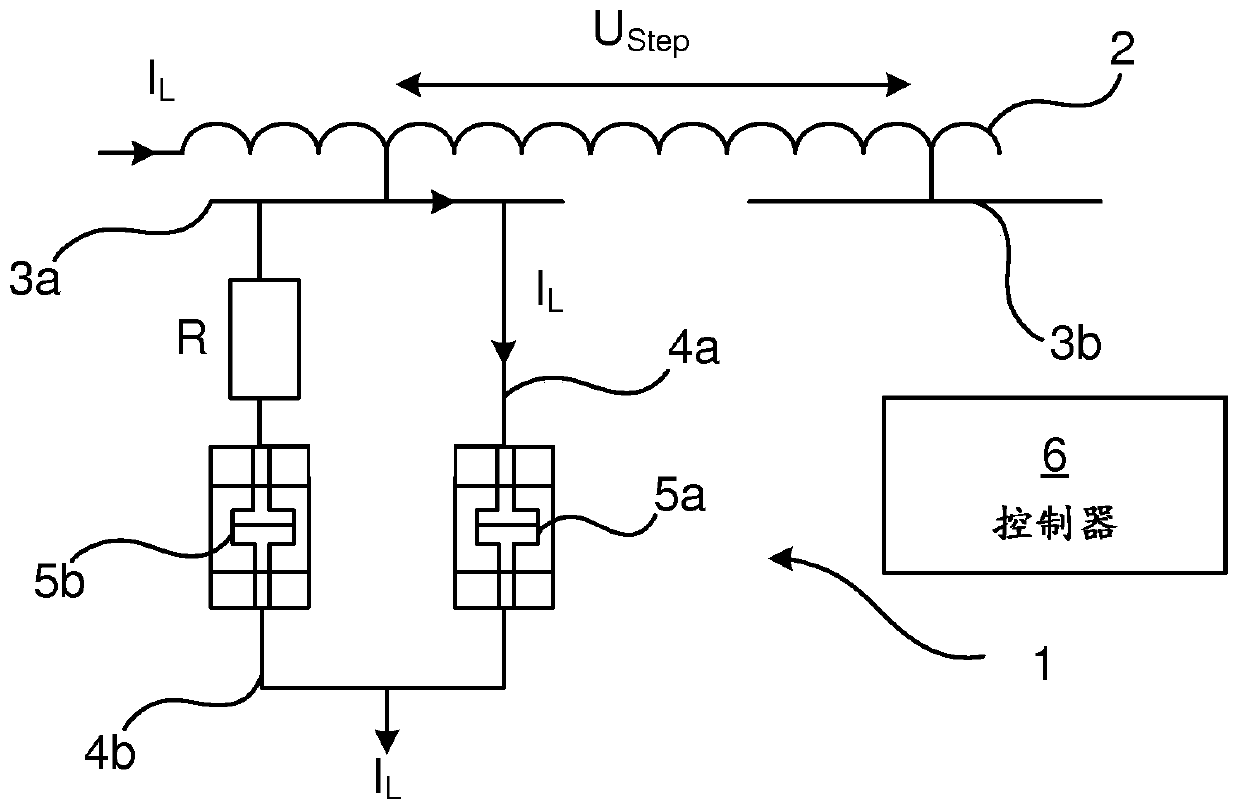
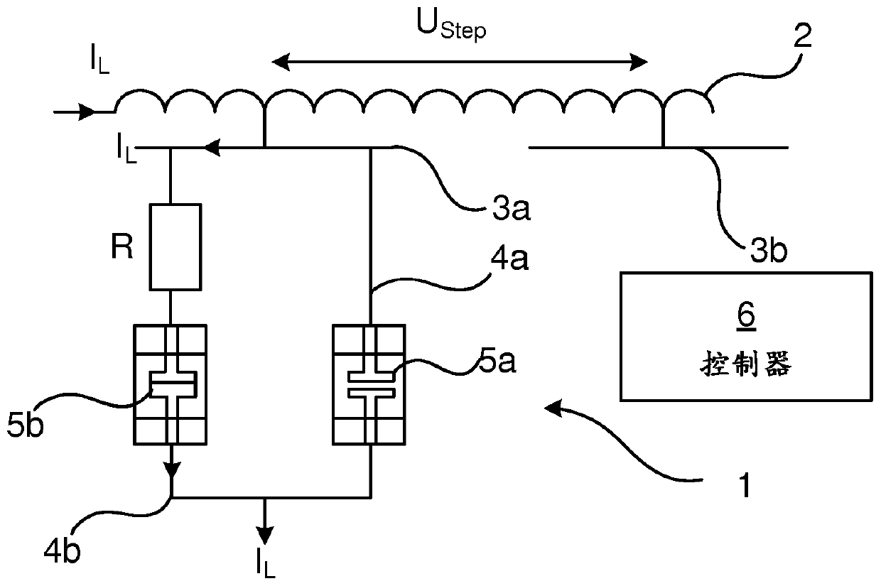
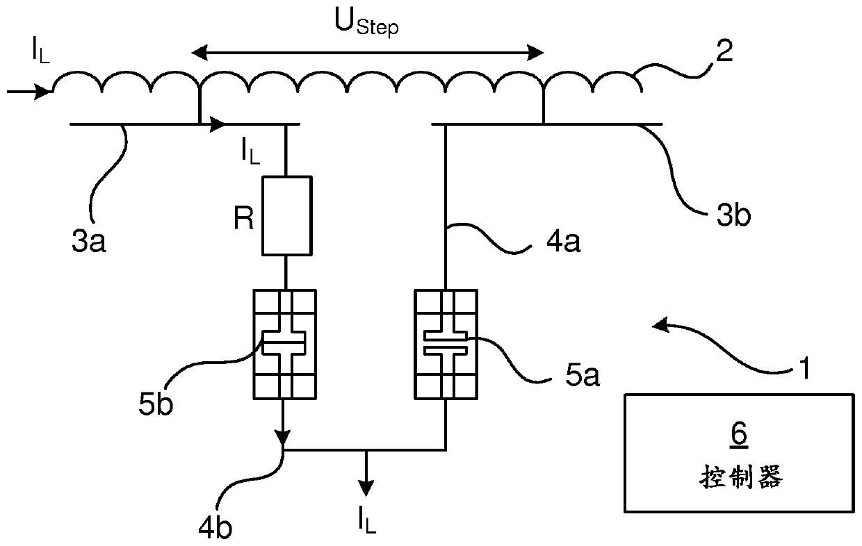
[0023] Figure 1a-Figure 1d The tap changer 1 is illustrated when the changeover switch of the tap changer is switched from the first contact 3a to the second contact 3b for different taps on the winding 2 of the transformer, on the primary side or the secondary side of the transformer. (usually an on-load tap changer (OLTC)) at different steps in switching. The transformer winding 2 may have any number of contacts 3, each contact 3 corresp...


PUM


Abstract

The present disclosure relates to a method of monitoring switching by an on-load tap changer (OLTC) (1) from a first contact (3a) to a second contact (3b) of a transformer winding (2). The method comprises measuring a voltage of the transformer. The method also comprises measuring a temperature of the OLTC. The method also comprises, based on the measured voltage and temperature, determining whether the switching from the first contact to the second contact has been successful.

Description

technical field [0001] The present disclosure relates to a method of monitoring switching of an on-load tap changer (OLTC) from a first contact to a second contact of a transformer winding tap. Background technique [0002] A transformer tap is a connection point along a transformer winding that allows a specific number of turns to be selected. This means creating a transformer with variable turns ratio, thus enabling voltage regulation of the output. Tap selection is done via a tap changer mechanism. A tap changer is a device comprising a tap selector and a diverter switch capable of rapidly moving between different contacts, wherein when the tap changer is on-load (without stopping the operation of the transformer), the Switching resistors are used to mitigate switching states where the switch moves between different contacts. Tap changers can also be designed with combined shunt switches and tap selectors (selector switch type). [0003] There is a need to detect whet...

Claims


Application Information

Patent Timeline
IPC IPC(8): H02H7/055H01F29/04
CPCH01F29/04H02H7/055H01H2009/0061G01R31/62H02P13/06H01F29/02H01H9/0005H02H1/0007
Inventor B-O·斯特尼斯塔姆
Owner HITACHI ENERGY SWITZERLAND AG
Why Eureka
Try Eureka