
LED driver, LED light-emitting circuit and LED light source

A technology of LED driver and light-emitting circuit, which is applied in the LED field, can solve the problems of space occupation and high manufacturing cost, and achieve the effects of simplifying the circuit, reducing manufacturing cost, and reducing space occupation

Inactive Publication Date: 2009-09-09
THE HONG KONG POLYTECHNIC UNIV
View PDF5 Cites 4 Cited by
  • Summary
  • Abstract
  • Description
  • Claims
  • Application Information

AI Technical Summary

Problems solved by technology

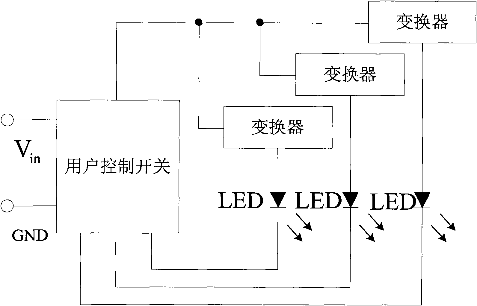
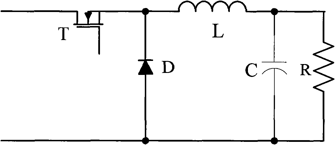
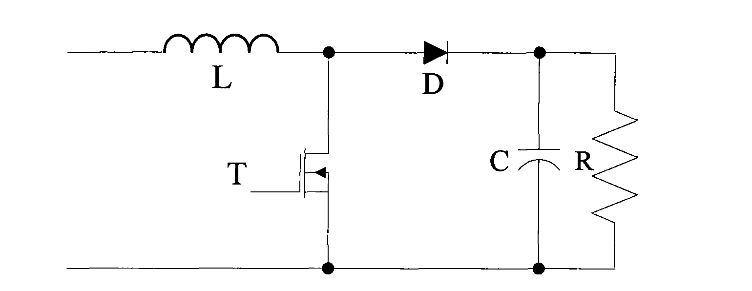
[0005] It can be seen that the switching power supplies used as LED drivers in the prior art all include at least an active switch, a diode, an inductor and a capacitor, which have the problems of high space occupation and manufacturing cost, and the more components, the required The more factors considered

Method used


Image

  • LED driver, LED light-emitting circuit and LED light source
  • LED driver, LED light-emitting circuit and LED light source
  • LED driver, LED light-emitting circuit and LED light source

Examples


Embodiment Construction

[0030] Specific embodiments of the present invention will be described in detail below. It should be noted that the embodiments described here are for illustration only, and are not intended to limit the present invention.

[0031] First of all, it must be explained that the core idea of ​​the present invention is to reduce the internal components of the traditional DC / DC converter on the premise of maintaining the LED luminous effect. The principle is based on the characteristics of human vision, that is, human perception of light changes There is a certain delay, and any change faster than the reaction time of the human eye will not be noticed.

[0032] In general, since the internal components of the switching power supply work in a high-frequency switching state, if there is enough magnetic inductance coefficient of the circuit, the driving of the LED can be realized; based on this principle, some components in the traditional DC / DC converter, such as Capacitors and diode...


PUM


Abstract

The invention discloses an LED driver, which comprises an active switch, an inductor and a capacitor. The active switch, the inductor and the capacitor adopt a connection structure which makes the active switch, the inductor and the capacitor connected with a diode to form a switching power circuit; inductor output of the LED driver is used for driving an LED arranged at the position of the diode; and the LED driver controls luminous intensity of the LED by controlling a load cycle of the active switch. The invention also discloses other two LED drivers, the active switch and the inductor and the diode adopt a connection structure which makes the active switch and the inductor and the diode connected with a capacitor to form a Buck switching power circuit, or the active switch and the inductor adopt a connection structure which makes the active switch and the inductor connected with the serially connected capacitor and diode to form the switching power circuit. The invention also discloses an LED light-emitting circuit and an LED light source. The invention does not influence the luminous effect of the LED, and simultaneously is favorable for circuit simplification so as to reduce the space occupation and the manufacturing cost.

Description

technical field [0001] The invention relates to the technical field of LEDs, in particular to an LED driver, an LED lighting circuit and an LED light source. Background technique [0002] Currently, high-power LEDs (Light Emitting Diodes, Light Emitting Diodes) are widely used as effective light sources, for example, in headlights and taillights of automobiles. As an LED driver, it is required to provide a voltage higher than the forward voltage of the LED, and to be able to limit the current within the working range of the LED. [0003] The traditional DC / DC power converter can meet the above requirements of LED, and it is an ideal LED driver. Please refer to figure 1 , showing its drive circuit as an LED driver to power LEDs in automotive headlights and taillights. [0004] Among them, the Switching Mode Power Supply (SMPS) converter is a high-efficiency and energy-saving DC / DC power converter, and its types include Buck (step-down), Boost (boost), Buck-Boost (reverse) ...

Claims


Application Information

Patent Timeline
Patent Type & Authority Applications(China)
IPC IPC(8): H05B37/02F21V23/00F21S8/10F21W101/02F21Y101/02F21W107/10F21Y115/10
Inventor 郑家伟郑绮君祁树刚张宙郭锦辉
Owner THE HONG KONG POLYTECHNIC UNIV
Learn More