
Automatic cleaning device for fan coil

A fan coil unit and automatic cleaning technology, which is applied in the directions of cleaning methods, cleaning methods and utensils, chemical instruments and methods using liquids, etc., can solve the problems of complicated operation and low efficiency, and achieves solving the difficulty of manual cleaning and reducing labor costs. And the effect of maintenance cost and after-sales maintenance convenience

Pending Publication Date: 2019-07-19
JIANGSU TEKENENNA ENERGY SAVING TECH
View PDF6 Cites 1 Cited by
  • Summary
  • Abstract
  • Description
  • Claims
  • Application Information

AI Technical Summary

Problems solved by technology

[0005] Purpose of the invention: The purpose of the present invention is to solve the problem that the fan coil part of the central air-conditioning indoor unit needs to be disassembled for cleaning the fins of the existing air-conditioning indoor unit, the operation is complicated and the efficiency is quite low

Method used


Image

  • Automatic cleaning device for fan coil
  • Automatic cleaning device for fan coil
  • Automatic cleaning device for fan coil

Examples


Embodiment 1

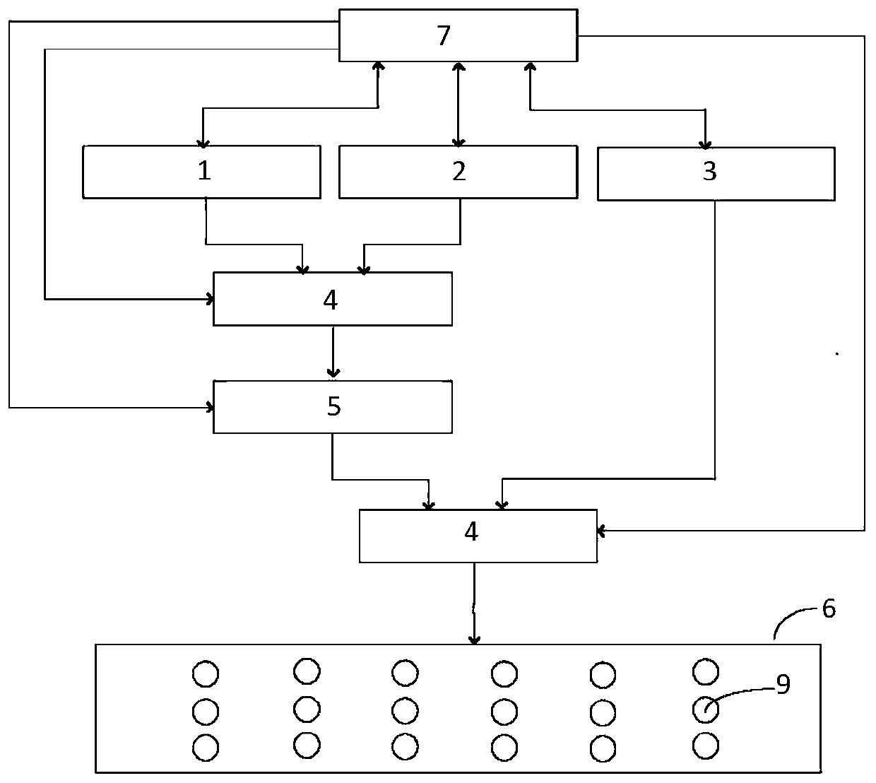
[0037] By adopting the technical solution of this embodiment, the spraying surface of the spraying device is as close as possible to the area where the fins are distributed, spray holes are spread all over the spraying surface, and spraying is performed by water pressure.

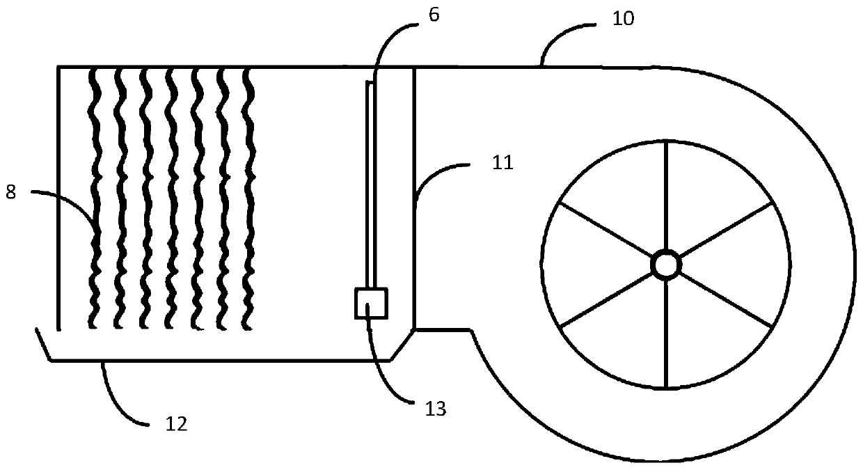
[0038] An automatic cleaning device for a fan coil unit, comprising an automatic cleaning agent replenishment device 1, an automatic water flushing device 2, a high-pressure steam disinfection device 3, two three-way solenoid valves 4, a motor 5, and a spraying device 6; an automatic cleaning agent replenishment device 1. Automatic water flushing device 2, high-pressure steam disinfection device 3, two three-way solenoid valves 4 and motor 5 are all connected to the controller 7 and power supply (not shown), and the spraying device 6 has a nozzle facing the inner fin 8 of the fan coil unit. Jet hole 9.

[0039] The spraying device 6 is arranged between the fan 10 and the fins 8 in the fan coil unit.

[004...

Embodiment 2

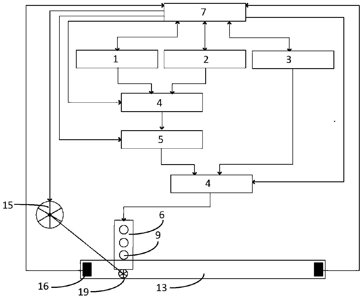
[0057] An automatic cleaning device for a fan coil unit, comprising an automatic cleaning agent replenishment device 1, an automatic water flushing device 2, a high-pressure steam disinfection device 3, two three-way solenoid valves 4, a motor 5, and a spraying device 6; an automatic cleaning agent replenishment device 1. Automatic water flushing device 2. High-pressure steam disinfection device 3. Two three-way solenoid valves 4 and motor 5 are connected to controller 7 and power supply (not shown). Jet hole 9. It also includes a moving track 13 arranged between the fan 10 in the fan coil unit and the fin 8 along the extending direction of the fin 8. There is a chute (not shown) for at least one roller 14 to slide on the moving track 13. The roller 1 passes through the roller shaft (not shown) and the impeller 15 arranged in front of the water inlet of the motor 5. Specifically, there are convex teeth on the roller shaft, and the convex teeth cooperate with the elliptical cha...


PUM


Abstract

The invention discloses an automatic cleaning device for a fan coil. The automatic cleaning device comprises an automatic cleaning agent supplementing device, an automatic clean water flushing device,a high-pressure steam disinfection device, two three-way solenoid valves, a motor and a spraying device; and the automatic cleaning agent supplementing device, the automatic clean water flushing device, the high-pressure steam disinfection device, the two three-way solenoid valves and the motor are all connected to a controller and a power supply. By adopting the automatic cleaning device, the spraying device can be pre-arranged between a fan and fins in the air conditioner fan coil, and is provided with spraying holes facing the fins, thus the fins can be automatically cleaned, sewage can becollected by forming holes in the bottom of the air conditioner fan coil, and the fins can be cleaned without disassembling the fan coil any more.

Description

technical field [0001] The invention relates to an automatic cleaning device for a fan coil unit, which is applied in the field of electrical automatic control. This technology applies the physical structure to the indoor unit of the central air conditioner. [0002] technical background [0003] Fan coil unit is an ideal terminal product of central air-conditioning, mainly composed of coil unit and fan, widely used in hotels, office buildings, hospitals, commercial and residential, scientific research institutions and other places. [0004] There are hundreds or even thousands of fan coil units in large places, and these fan coil units work for a long time, and the fins of the fan coil units often produce a lot of dirt and bacteria. After-sales maintenance personnel need to regularly clean the fins of the coil part twice a year. However, the fan part of the fan coil needs to be removed for manual cleaning. Screws, steel plates, fans, etc. are disassembled and installed. Bot...

Claims


Application Information

Patent Timeline
Patent Type & Authority Applications(China)
IPC IPC(8): B08B3/08B08B3/02A61L2/07
CPCB08B3/08B08B3/024A61L2/07A61L2202/17
Inventor 张红星宁方亮宁尚超吴玉娇费晟珏
Owner JIANGSU TEKENENNA ENERGY SAVING TECH
Learn More