Relay base automatic assembly line

An automatic assembly and production line technology, applied in assembly machines, workpiece clamping devices, metal processing equipment, etc., can solve the problems of small size of the conductive sheet parts of the shell, small size of the small relay base, and displacement of the assembly position of the shell terminals.

Active Publication Date: 2021-03-05
WENZHOU DRESDNER AUTOMATION TECH CO LTD
View PDF6 Cites 0 Cited by
  • Summary
  • Abstract
  • Description
  • Claims
  • Application Information

AI Technical Summary

Problems solved by technology

[0003] In the production process of the relay base, the general production process is to first produce the corresponding shell, the internal conductive sheet parts and the cover, and then complete the production of the relay base by assembling. The existing small relay base is relatively large in size. Small, the volume of the corresponding shell and internal conductive sheet parts is also relatively small, so it is more difficult in the assembly process. In order to ensure the efficiency and yield of assembly, the existing equipment is generally used to realize automatic assembly. Existing equipment It is all done by setting up a conveyor belt to transport the shells that need to be assembled, and then setting up the assembly devices for the parts that need to be gradually assembled into the shells along the conveyor belt. , to assemble the terminals into the housing one by one. However, the existing relay housing is not a regular quadrilateral. When the housing is placed on a flat conveyor belt, it is easier to have the problem that the housing is not placed flat enough. During the process, it is easy to have the problem that the position of the terminal assembly is shifted due to the shift of the shell position

Method used


Image

  • Relay base automatic assembly line
  • Relay base automatic assembly line
  • Relay base automatic assembly line

Examples


Embodiment Construction

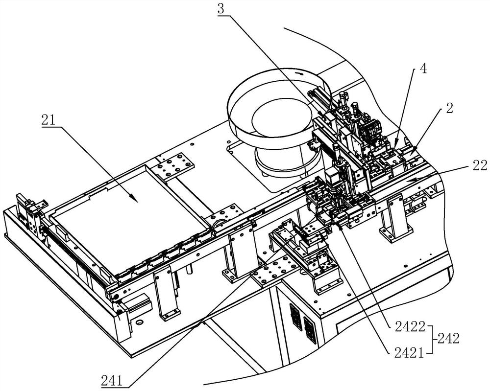
[0018] The present invention will be described in further detail below in conjunction with the embodiments given in the accompanying drawings, wherein the moving parts of the power part not mentioned in this embodiment, such as the sliding base 2421, the clamping seat 321, etc., all use cylinders as The power component, so the principle of its action will not be repeated in this embodiment.

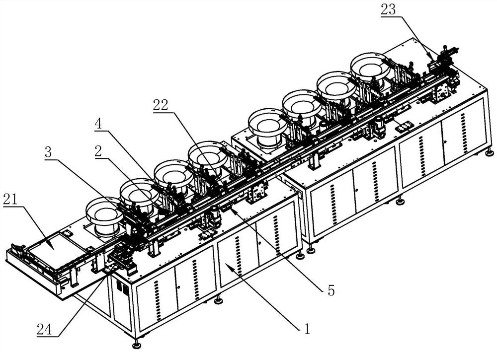
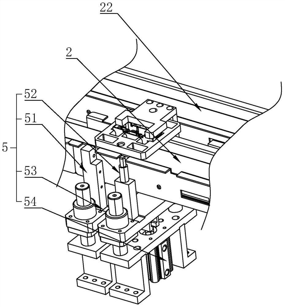
[0019] refer to Figures 1 to 4 As shown, a relay base automatic assembly production line in this embodiment includes a frame 1, a conveyor belt 2 and several component assembly devices 3 all arranged on the frame 1, and several component assembly devices 3 are arranged along the conveyor belt. 2 The longitudinal direction is evenly spaced from each other, and the clamp base 4 is placed on the conveyor belt 2, and the positioning device 5 for positioning the clamp base 4 is provided below the conveyor belt 2 relative to the assembly device 3 of each component. When assembling , the housi...


PUM


Abstract

The invention discloses an automatic assembly production line for a relay base. The automatic assembly production line comprises a frame, a conveying belt and a plurality of component assembly devices, wherein the conveying belt and the plurality of component assembly devices are all arranged on the frame; a clamp base is arranged on the conveying belt; a positioning device for positioning the clamp base is arranged at a position, corresponding to each component assembly device, below the conveying belt; and when in assembling, a shell is placed on the clamp base, the clamp base is driven by the conveying belt to move below the component assembly devices one by one, the clamp base is positioned by the positioning devices, and a component is assembled by the component assembly devices intothe shell. According to the automatic assembly production line for the relay base, through the arrangement of the clamp base and the positioning devices, the shell can be effectively positioned when the component is placed into the shell, and the problem that the component cannot be well placed into the shell due to the offset position of the shell in the prior art is effectively solved.

Description

technical field [0001] The invention relates to an assembly equipment, more specifically to an automatic assembly production line for a relay base. Background technique [0002] In the process of using the relay, a relay base is generally set up to connect with the external circuit. On the one hand, the multiple connectors required on the relay can be connected in a centralized manner to avoid the problem of cluttered lines. On the other hand, it can It is convenient to replace the relay. [0003] In the production process of the relay base, the general production process is to first produce the corresponding shell, the internal conductive sheet parts and the cover, and then complete the production of the relay base by assembling. The existing small relay base is relatively large in size. Small, the volume of the corresponding shell and internal conductive sheet parts is also relatively small, so it is more difficult in the assembly process. In order to ensure the efficienc...

Claims


Application Information

Patent Timeline
Patent Type & Authority Patents(China)
IPC IPC(8): B23P19/00B23P21/00B25B11/02
CPCB23P19/00B23P19/001B23P21/00B25B11/02
Inventor 刘德彬
Owner WENZHOU DRESDNER AUTOMATION TECH CO LTD
Why Eureka
Try Eureka