Autonomous inspection and DTRF identification and control robot for unattended relay protection room

A protection room and robot technology, applied in the direction of manipulators, manufacturing tools, etc., can solve problems such as poor anti-environmental interference, low sensitivity, low reliability, and deviation of internal component characteristics

Pending Publication Date: 2019-07-19
ZHEJIANG UNIV OF TECH
View PDF0 Cites 7 Cited by
  • Summary
  • Abstract
  • Description
  • Claims
  • Application Information

AI Technical Summary

Problems solved by technology

The capital investment is large, the transformation period is long, and there are many problems in the current online monitoring system: a. The ability to resist environmental interference is poor, the sensitivity and reliability are low, and the dielectric loss value of the equipment fluctuates greatly with the temperature; b. System maintenance work Large quantity, low reliability, and large deviations in internal component characteristics over time; c. There are limitations, such as only measuring insulation parameters at power frequency operating voltages, and unable to measure parameters of power equipment at higher operating voltages
[0008] The above two measures have a common problem, which is that the operation of electrical equipment cannot be completed. In the event of equipment failure, line maintenance and other accidents, the staff still need to go to the relay protection room of the substation or distribution station to check the equipment in the corresponding panel cabinet. The switch is operated manually, and the loss is still unavoidable

Method used


Image

  • Autonomous inspection and DTRF identification and control robot for unattended relay protection room
  • Autonomous inspection and DTRF identification and control robot for unattended relay protection room
  • Autonomous inspection and DTRF identification and control robot for unattended relay protection room

Examples


Embodiment Construction

[0026] Further illustrate the present invention below in conjunction with accompanying drawing.

[0027] Referring to the attached picture:

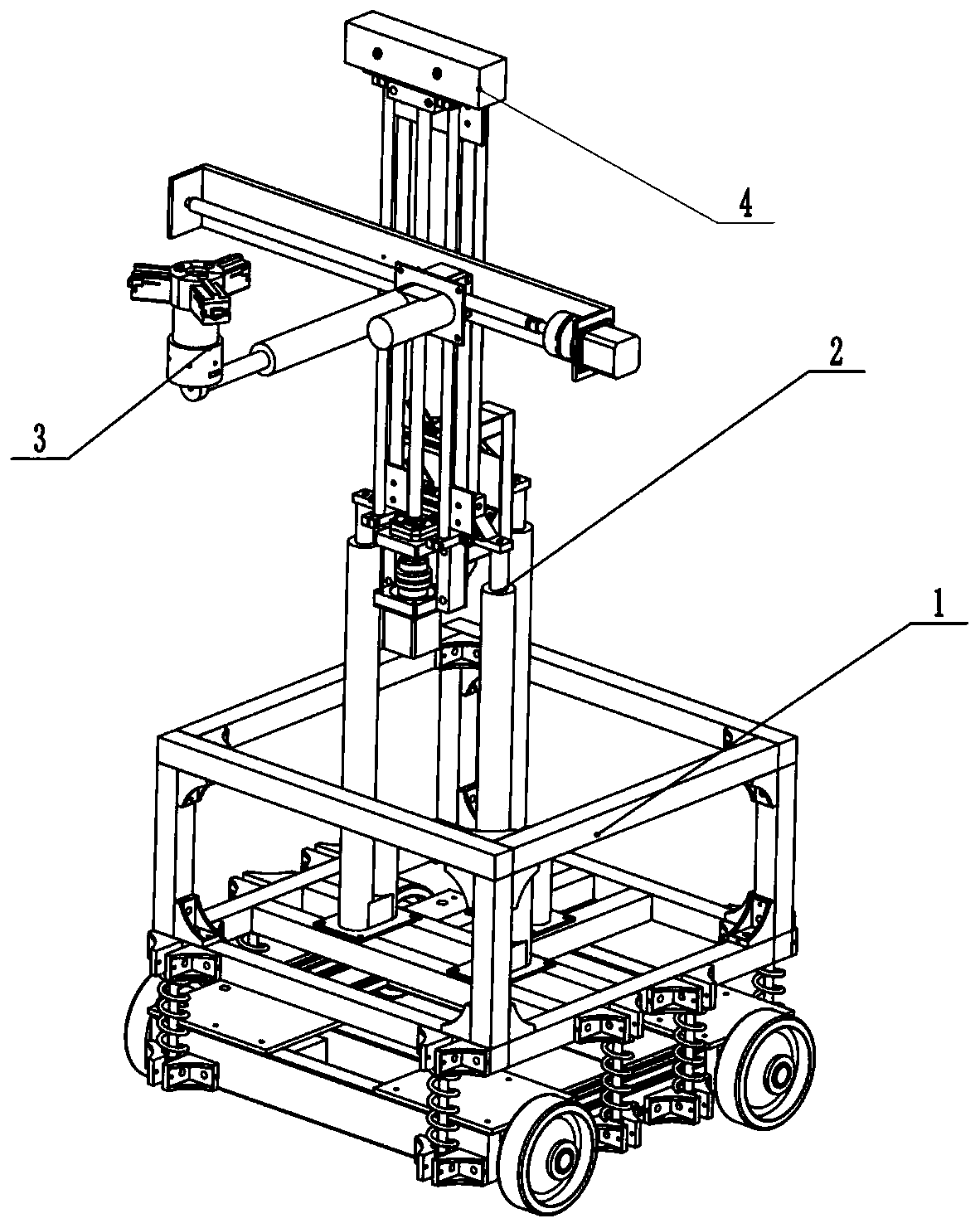
[0028] refer to figure 1 ~Figure, Embodiment 1 The autonomous inspection of unmanned relay protection room and DTRF identification and control robot according to the present invention, including: omnidirectional mobile device 1, two-stage three-axis mobile device 2, three-station multi-functional execution terminal The conversion device 3 and the camera 4, the two-stage three-axis moving device 2 is installed on the omni-directional moving device 1, and the three-station multifunctional execution end conversion device 3 is connected to the free end of the two-stage three-axis moving device 2, the The camera 4 is fixed on the top of the two-stage three-axis moving device 2 .

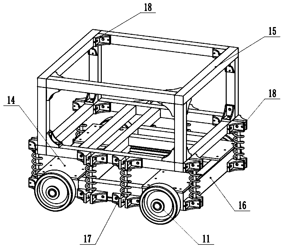
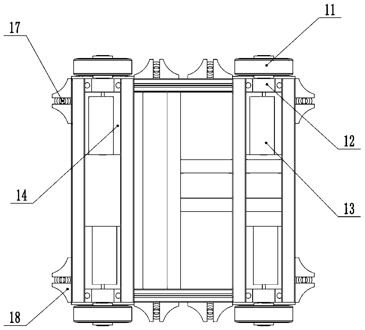
[0029] refer to figure 2 , image 3 , Omni-directional mobile device 1 includes Mecanum wheel 11, bearing support 12, stepping motor 13, iron sheet 14, aluminu...


PUM


Abstract

The invention discloses an autonomous inspection and DTRF identification and control robot of for an unattended relay protection room. The autonomous inspection and DTRF identification and control robot includes an omni-directional moving device, a two-section three-axis moving device, a three-station multi-function performing terminal conversion device and a camera, wherein the two-section three-axis moving device is installed on the omni-directional moving device, the three-station multi-function performing terminal conversion device is connected to the free end of the two-section three-axismoving device, and the camera is fixed to the top of the two-section three-axis moving device. According to the autonomous inspection and DTRF identification and control robot of for the unattended relay protection room, the camera is used for visual navigation, and a designated position is reached through the omni-directional moving device to achieve a moving function of the unattended room; theswitch positions of the equipment at different heights are reached through the two-section three-axis moving device; and different types of equipment switches are operated by the three-station multi-function performing terminal switching device, so that manual work is effectively replaced.

Description

technical field [0001] The invention relates to an autonomous inspection and DTRF identification control robot for an unmanned relay protection room. Background technique [0002] The relay room is the area where substations, converter stations, secondary screen cabinets and automatic devices of power plants are placed and arranged. Its important position can be compared to the nerves and brains of substations. The safe and stable operation of secondary equipment plays an important role in the overall safe operation and maintenance of substations. play a decisive role. [0003] At present, the substation of the State Grid adopts the operation and maintenance method of manual inspection. The technicians need to have both solid professional knowledge and long-term practical experience. According to the equipment inspection system of a 330kV substation, the inspection is not less than four times a day, including full-time inspection at night. Turn off the lights of the station...

Claims


Application Information

Patent Timeline
Patent Type & Authority Applications(China)
IPC IPC(8): B25J5/00B25J19/00
CPCB25J5/00B25J5/007B25J19/00
Inventor 郭千毅沈宽戴犇辉张永健周哲源李道政傅安凯冯书阅曾晰
Owner ZHEJIANG UNIV OF TECH
Why Eureka
Try Eureka