Cooling tank for rubber production

A cooling tank and rubber technology, applied in the field of rubber production, can solve the problem of inconvenient use of the cooling tank, and achieve the effect of reducing production costs

Inactive Publication Date: 2019-07-19
席早明
View PDF6 Cites 3 Cited by
  • Summary
  • Abstract
  • Description
  • Claims
  • Application Information

AI Technical Summary

Problems solved by technology

[0004] The object of the present invention is to provide a cooling tank for rubber production, which has the advanta

Method used


Image

  • Cooling tank for rubber production
  • Cooling tank for rubber production
  • Cooling tank for rubber production

Examples


Example

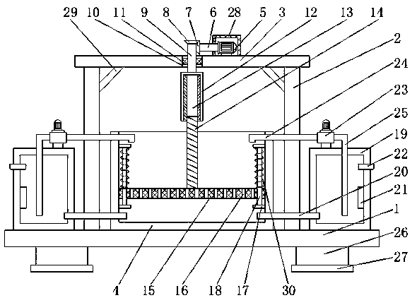
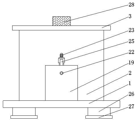
[0018] The first embodiment: please refer to Figure 1-2 , A cooling tank for rubber production, including a bottom plate 1, the left and right sides of the top of the bottom plate 1 are fixedly connected with support plates 2, the tops of the two support plates 2 are fixedly connected by the top plate 3, the left and right sides of the bottom of the top plate 3 are located The position between the two support plates 2 is fixedly connected to the limit rod 29, and the end of the limit rod 29 away from the top plate 3 is fixedly connected to the support plate 2. The top plate 3 and the support plate 2 are reinforced by setting the limit rod 29 The top of the bottom plate 1 and the position between the two support plates 2 is fixedly connected with a cooling shell 4, the top of the top plate 3 is fixedly connected with a drive motor 5, and the output shaft of the drive motor 5 is fixedly connected with a drive shaft 6, The top of the top plate 3 is provided with a dust-proof hous...

Example

[0021] The second embodiment: as described in claim 1, a cooling tank for rubber production, comprising a bottom plate 1, the left and right sides of the top of the bottom plate 1 are fixedly connected with support plates 2, and the tops of the two support plates 2 pass The top plate 3 is fixedly connected, the top of the bottom plate 1 and the position between the two supporting plates 2 is fixedly connected with a cooling shell 4, the top of the top plate 3 is fixedly connected with a drive motor 5, and the output shaft of the drive motor 5 A drive shaft 6 is fixedly connected to the upper part, a first gear 7 is fixedly connected to the left side of the drive shaft 6, a second tooth 8 is provided on the left side of the first wheel 7, and the first gear 7 and the second gear 8 are meshed with each other, the bottom of the second gear 8 is fixedly connected with a fixed rotating shaft 9, the top of the top plate 3 is provided with a through groove 10 that is adapted to the fix...


PUM


Abstract

The invention discloses a cooling tank for rubber production. The cooling tank for rubber production comprises a bottom plate. Supporting plates are fixedly connected to the left and right sides of the top of the bottom plate, tops of the two supporting plates are fixedly connected through a top plate, and a cooling shell is fixedly connected between the two supporting plates on the top of the bottom plate. By matching the cooling shell, a driving motor, a driving rotating shaft, a first gear, a second gear, a fixed rotating shaft, a threaded groove, a threaded rod a connecting plate, a connecting block, a sliding rod, a cooling tank, a water through pipe, a refrigerating block, a water injection pipe and a water pump, according to the lead screw principle, the threaded rod dries the connecting plate to move upward, so that a rubber product is taken conveniently. Then cold water in the cooling tank is introduced into the cooling shell by way of circulation through a water pump withoutreplacing water frequently, so that the rubber product can be cooled, the production cost is lowered, and great convenience is brought to rubber production work.

Description

technical field [0001] The invention relates to the technical field of rubber production, in particular to a cooling tank for rubber production. Background technique [0002] Rubber refers to a highly elastic polymer material with reversible deformation. It is elastic at room temperature, can produce large deformation under a small external force, and can return to its original shape after the external force is removed. Rubber is a completely amorphous polymer. Early rubber was latex taken from plants such as rubber trees and rubber grasses. After processing, it was made into materials with elasticity, insulation, impermeability and air. It is a high-elastic polymer compound. There are two types of natural rubber and synthetic rubber. Natural rubber is processed by extracting gum from rubber trees, rubber grass and other plants, and synthetic rubber is obtained by polymerization of various monomers. Rubber products refer to the production of various rubber products using n...

Claims


Application Information

Patent Timeline
IPC IPC(8): B29C35/16B29C48/885
CPCB29C35/16B29C48/885B29C2035/1616
Inventor 席早明
Owner 席早明
Why Eureka
Try Eureka