Quick overall foaming device and method for vehicle-mounted tank

A foaming device and tank technology, which is applied in the field of liquid tank trucks and fire trucks, can solve the problems that the overall quality of foaming is difficult to control, affects the insulation effect, and the density of foamed polyurethane insulation layer and the foaming hollow rate are unstable. Achieve the effect of reducing the risk of stripping, reducing production costs, and facilitating and quick installation

Pending Publication Date: 2019-07-19
滁州永强汽车制造有限公司
View PDF4 Cites 2 Cited by
  • Summary
  • Abstract
  • Description
  • Claims
  • Application Information

AI Technical Summary

Problems solved by technology

[0002] At present, in the field of vehicle-mounted tank foaming, the split-off mode foaming method is mostly used. The main reason is that there is a lack of overall foaming technology and methods for vehicle-mounted tanks. The density of the foamed polyurethane insulation layer and the foaming hollow rate are unstable. The overall quality of foaming is difficult to control. In addition, the overall structure of the vehicle-mounted tank is relatively complicated. The bottom of the square tank and the sides of the tank are concave, the sides of the tank near the bottom are arc-shaped, and the exposed connecting pipe on the tank is in line with the method. There are many blues, and there is currently no integral foaming device that can realize the above-mentioned tank structure
[0003] The production efficiency of split-type demoulding and foaming is low, and the insulation layer formed after polyurethane foaming is easy to separate from the tank wall, which affects the insulation effect; in addition, in order to ensure that the foamed insulation layer does not peel off from the tank wall The problem is that it is necessary to coat the outer wall of the tank with a strong adhesive paint before foaming to enhance the bonding between the insulation layer and the tank wall; after foaming in pieces and pieces, it is easy to produce many splicing on the outer wall of the tank The seams must be filled with foam to avoid affecting the thermal insulation effect

Method used


Image

  • Quick overall foaming device and method for vehicle-mounted tank
  • Quick overall foaming device and method for vehicle-mounted tank
  • Quick overall foaming device and method for vehicle-mounted tank

Examples


Embodiment Construction

[0039] In order to further understand the content of the present invention, the composition and working process of the present invention will be described in detail in conjunction with the accompanying drawings.

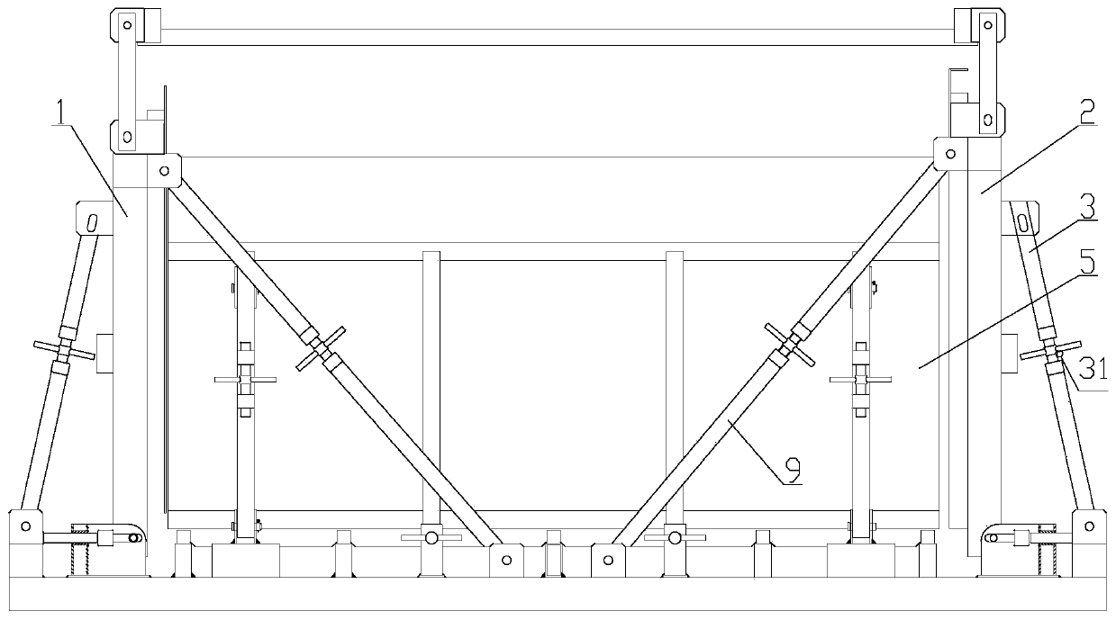
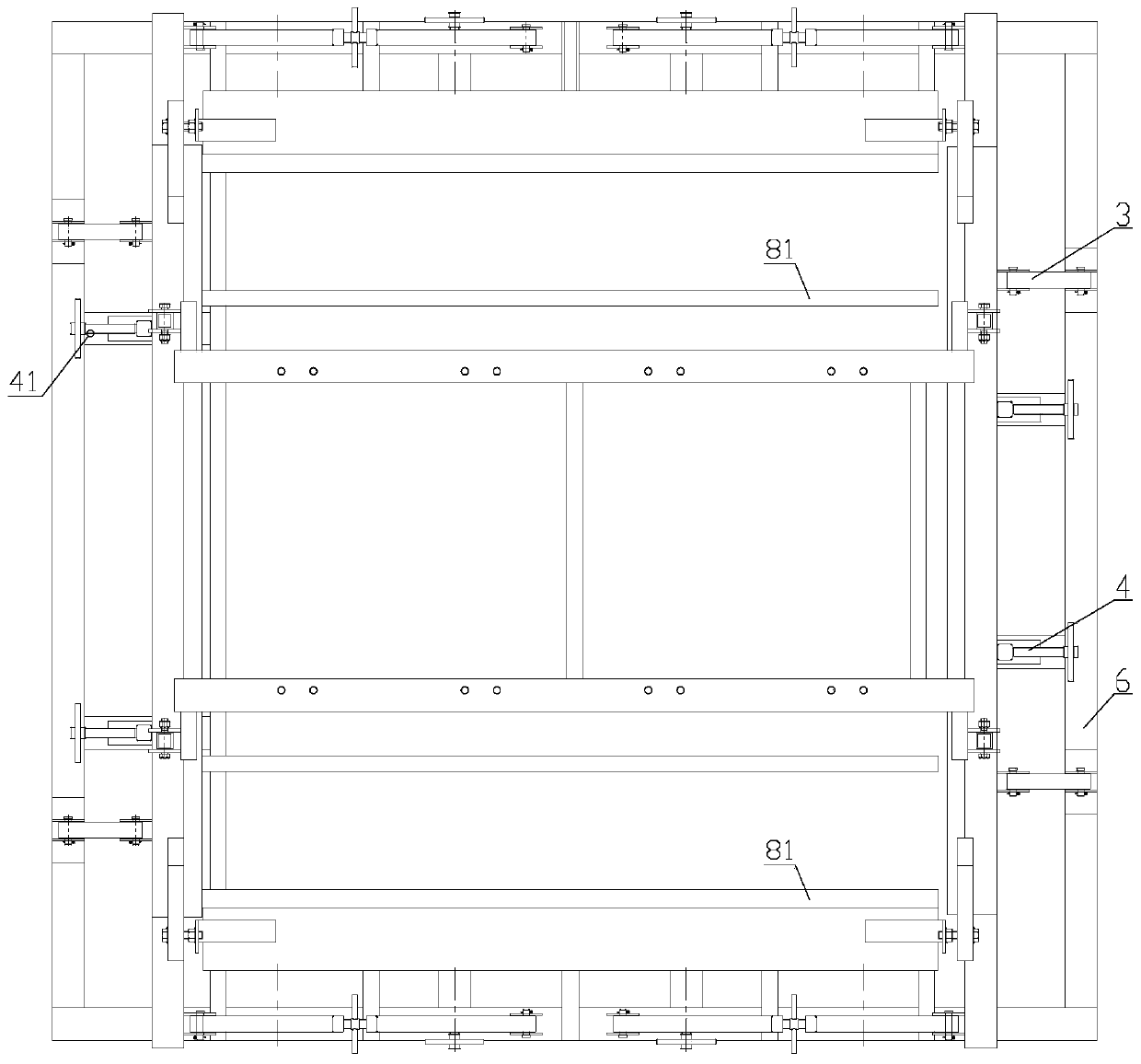
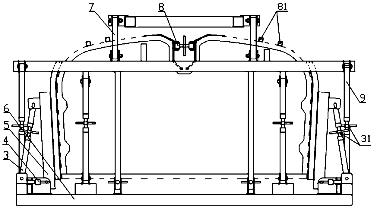
[0040] like Figure 1-Figure 3 As shown, the rapid overall foaming device for the tank body includes a front formwork 1, a rear formwork 2, a side formwork 5, a bottom frame 6, a support adjustment device 3, a push-pull adjustment device 4, a tank bottom beam connection frame 7, and a pull rod device 9. Bottom foaming tooling 8, front and rear mold bases and left and right side mold bases are installed on the base frame 6, eight push-pull adjustment devices 4 are connected to the four sides of the base frame, and one end of the eight support adjustment devices is connected to the base frame 6, The other end is connected with the front and rear formworks and the left and right side formworks respectively; the tie bar device 9 is two groups of four sets located at both...


PUM


Abstract

The invention discloses a quick overall foaming device and method for a vehicle-mounted tank. The quick overall foaming device comprises front and rear mould frames, right and left side mould frames,an underframe, support regulating devices, push-pull regulating devices, tank bottom beam connecting frames, pull rod devices, a bottom foaming tool and the like. The secure connection between the mould frames and the underframe is achieved through the push-pull regulating devices, the support regulating devices and the pull rod devices, and the tank bottom beam connecting frames are located abovethe device; and the two ends of each tank bottom beam connecting frame are provided with movable rotary arms, and the front and rear mould frames are connected with the tank bottom beam connecting frames through the movable rotary arms. According to the quick overall foaming device and method, the overall foaming of tanks of different structures is achieved, and lots of work for joint filling andfoaming supplement generated by partitioning and fragmentation foaming is reduced, and the work efficiency is improved; and the production cost is reduced.

Description

technical field [0001] The invention belongs to the technical field of liquid tank trucks and fire trucks, and in particular relates to a rapid integral foaming device and an integral foaming method for a vehicle-mounted tank body. Background technique [0002] At present, in the field of vehicle-mounted tank foaming, the split-off mode foaming method is mostly used. The main reason is that there is a lack of overall foaming technology and methods for vehicle-mounted tanks. The density of the foamed polyurethane insulation layer and the foaming hollow rate are unstable. The overall quality of foaming is difficult to control. In addition, the overall structure of the vehicle-mounted tank is relatively complicated. The bottom of the square tank and the sides of the tank are concave, the sides of the tank near the bottom are curved, and the exposed connecting pipe on the tank is in line with the method. There are many blues, and there is no integral foaming device that can real...

Claims


Application Information

Patent Timeline
Patent Type & Authority Applications(China)
IPC IPC(8): B29C44/18
CPCB29C44/188
Inventor 胡代刚王特夫黄炳辉李金龙
Owner 滁州永强汽车制造有限公司
Why Eureka
Try Eureka