Eureka AIR delivers breakthrough ideas for toughest innovation challenges, trusted by R&D personnel around the world.

Vacuum system high-efficiency liquid discharging device

A technology of a liquid drainage device and a vacuum system, which is applied in the directions of packaging, transportation, packaging, and containers, can solve the problems of vacuum environment damage, rising production costs, and increased labor intensity of operators, and achieves automatic and efficient liquid drainage and maintains a vacuum state. Effect

Active Publication Date: 2019-07-19
安徽晟捷新能源科技股份有限公司
View PDF8 Cites 1 Cited by
  • Summary
  • Abstract
  • Description
  • Claims
  • Application Information

AI Technical Summary

Problems solved by technology

[0002] When the existing vacuum system is draining, a part of the external air often enters the vacuum system from the draining device, causing damage to the internal vacuum environment. Vacuum, the number of liquid discharges is small, and it will not cause too much interference to the normal production. However, when the number of liquid discharges is large, frequent shutdowns will cause an increase in production costs, and at the same time, the labor intensity of operators will also increase.

Method used


Image

  • Vacuum system high-efficiency liquid discharging device
  • Vacuum system high-efficiency liquid discharging device
  • Vacuum system high-efficiency liquid discharging device

Examples


Embodiment Construction

[0029] In order to make the technical means, creative features, objectives and effects of the present invention easy to understand, the following will clearly and completely describe the technical solutions in the embodiments of the present invention with reference to the accompanying drawings in the embodiments of the present invention. Obviously, The described embodiments are only a part of the embodiments of the present invention, rather than all the embodiments. Based on the embodiments of the present invention, all other embodiments obtained by those of ordinary skill in the art without creative work shall fall within the protection scope of the present invention.

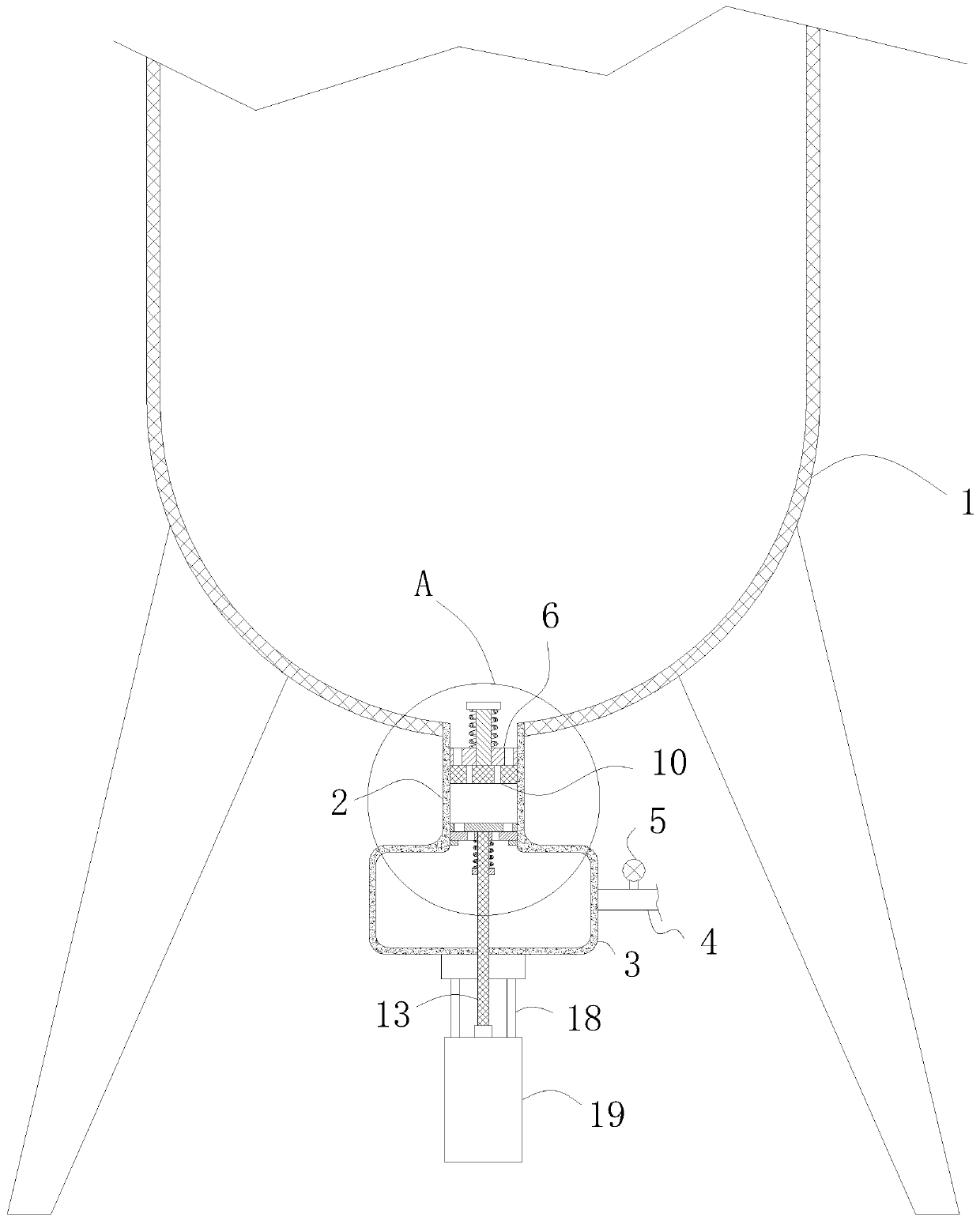
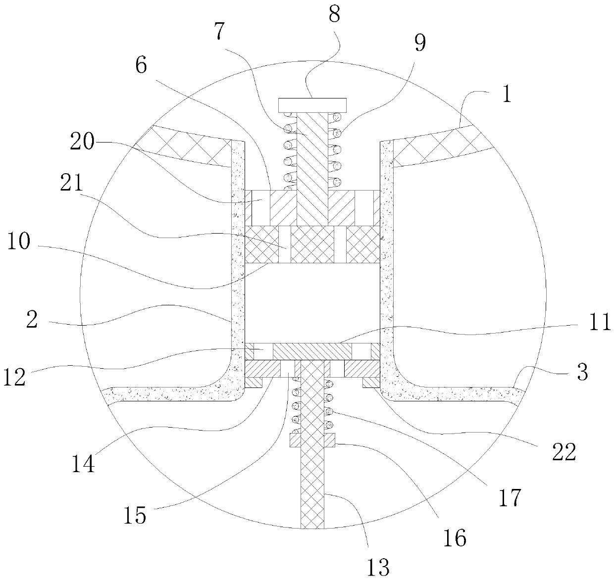
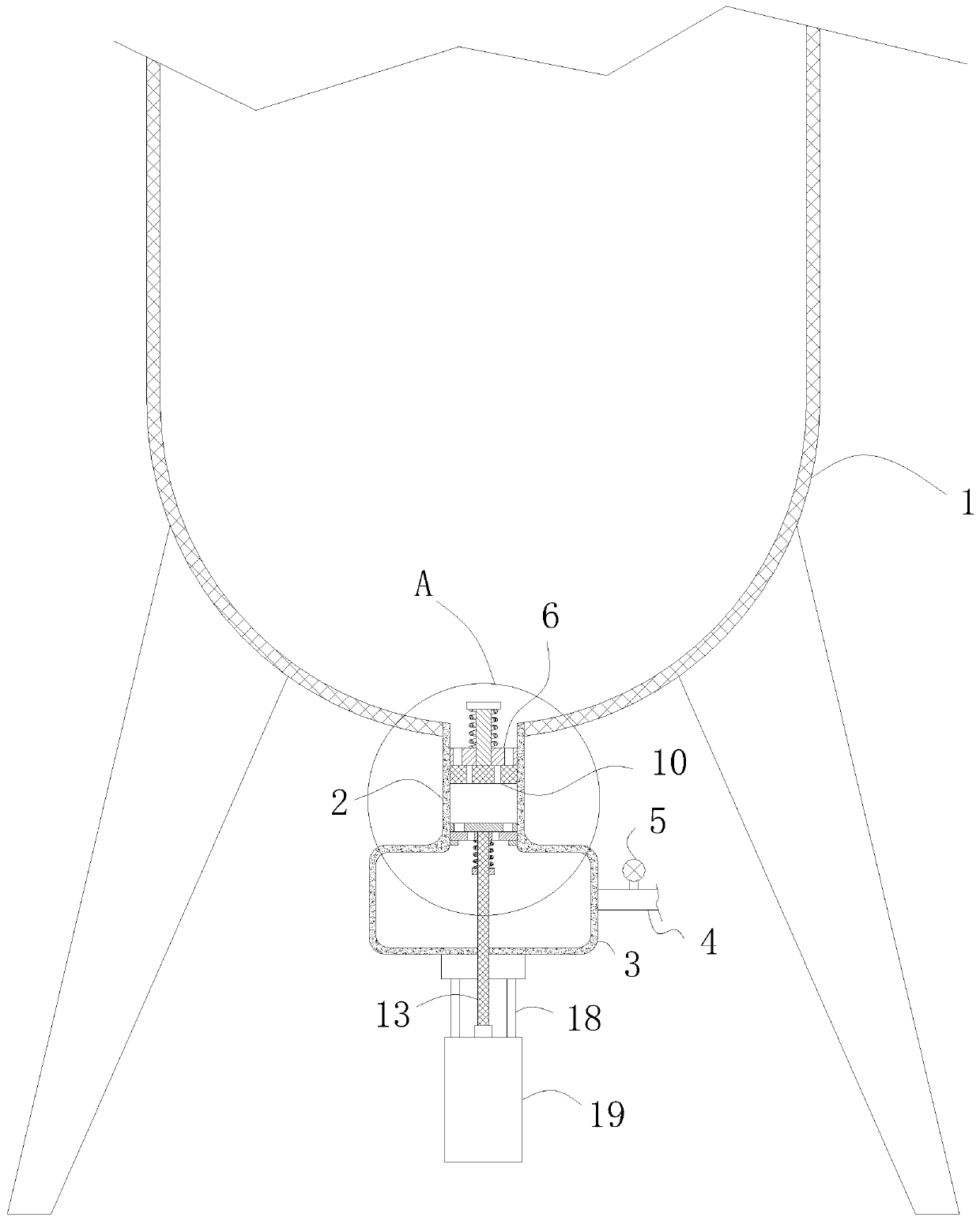
[0030] Such as Figure 1-2 The shown high-efficiency draining device for a vacuum system includes a vacuum tank 1, with a liquid outlet at the bottom of the vacuum tank 1, and further includes:

[0031] A liquid storage bin, the liquid storage bin is composed of a liquid inlet 2 and a liquid outlet 3, the liquid i...


PUM


Abstract

The invention relates to the technical field of vacuum equipment, in particular to a vacuum system high-efficiency liquid discharging device. The vacuum system high-efficiency liquid discharging device comprises a vacuum tank. The bottom of the vacuum tank is provided with a liquid outlet. The vacuum system high-efficiency liquid discharging device further comprises a liquid storage tank, a liquiddischarging pipe, a one-way electromagnetic valve, a stopper, a sliding rod, a limiting block, a first spring, a piston, a sliding plug, a driving rod, a floating plug, a limiting ring and a second spring. The vacuum system high-efficiency liquid discharging device has the beneficial effects that automatic and high-efficiency liquid discharge is achieved, in addition, external air cannot participate in the liquid discharging process, thus, the vacuum tank is in a vacuum state in the liquid discharging process, and the vacuum state of the vacuum system is maintained when the liquid dischargingoperation is conducted.

Description

Technical field [0001] The invention relates to the technical field of vacuum equipment, in particular to a high-efficiency draining device for a vacuum system. Background technique [0002] When the existing vacuum system is draining, a part of the external air will enter the vacuum system through the draining device, causing damage to the internal vacuum environment. At this time, it can only be shut down and the vacuum system is pumped again. Vacuum, the number of draining times is small, and will not cause much interference to the normal production. However, when the number of draining times is large, frequent shutdowns will cause the production cost to rise, and the labor intensity of the operators will also increase. Summary of the invention [0003] The purpose of the present invention is to overcome the problems in the prior art and provide a high-efficiency draining device for a vacuum system, which can realize that when the vacuum tank is draining, external air will not ...

Claims


Application Information

Patent Timeline
Patent Type & Authority Applications(China)
IPC IPC(8): B65D88/54B65D90/00
CPCB65D88/54B65D90/00
Inventor 涂张应肖彤张华
Owner 安徽晟捷新能源科技股份有限公司
Why Eureka
Eureka Blog
Learn More