ceiling fan

A ceiling fan and base technology, applied in the field of ceiling fans with drainage structure, can solve problems such as damage to electronic components, damp ceilings, water accumulation in ceiling fans, etc., and achieve the effects of improving convenience of use, prolonging service life, and reducing costs

Active Publication Date: 2020-08-28
SUNONWEALTH ELECTRIC MACHINE IND
View PDF6 Cites 0 Cited by
  • Summary
  • Abstract
  • Description
  • Claims
  • Application Information

AI Technical Summary

Problems solved by technology

[0003] However, when the existing ceiling fans are suspended on the indoor ceiling, because the ceiling often has problems of moisture and water seepage, water vapor easily penetrates into the interior of the ceiling fan; Therefore, when it is suspended in an open space, if it rains, since the ceiling fan does not have any other protection, rainwater will splash into the interior of the ceiling fan from all directions
Therefore, regardless of whether the existing ceiling fan is suspended indoors or outdoors, under long-term use, it is easy to cause water vapor deposition inside the ceiling fan to form water accumulation, and the water accumulation cannot be removed for a long time, which will cause internal electronic components to be damaged. Damaged by moisture, seriously affecting the service life of the existing ceiling fan

Method used


Image

  • ceiling fan
  • ceiling fan
  • ceiling fan

Examples


no. 1 example

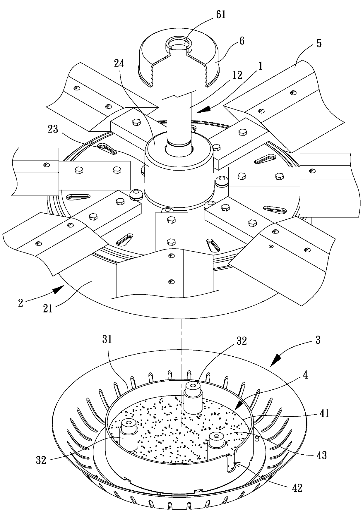
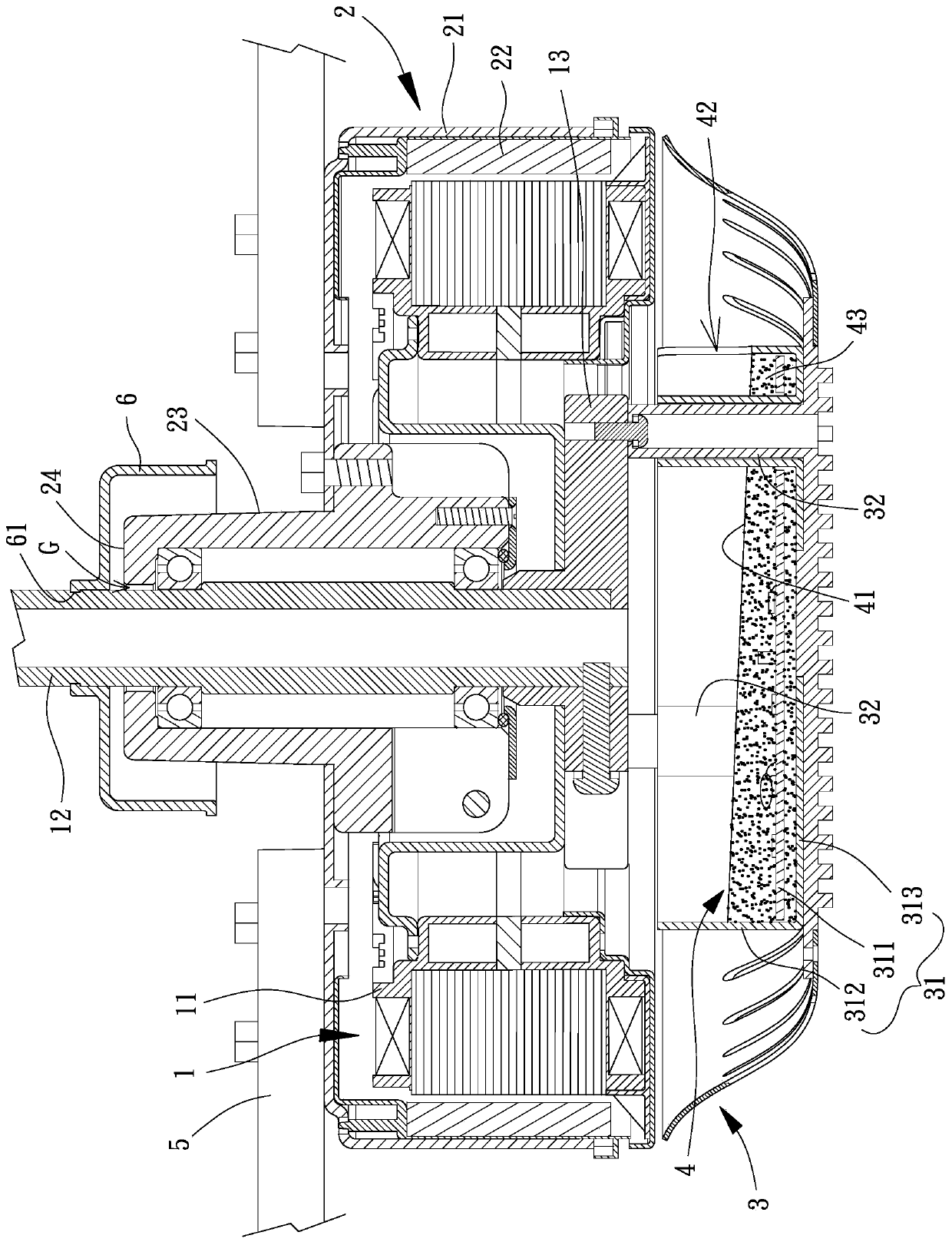
[0042] Please refer to figure 1 , which is the first embodiment of the ceiling fan of the present invention, the ceiling fan includes a stator 1, a rotor 2, a base 3, a drainage structure 4 and a plurality of fan blades 5, the rotor 2 is rotatably combined with the shaft The outer periphery of the rod 12 , the base 3 is combined with the stator 1 , the drainage structure 4 is disposed on the base 3 , and the plurality of fan blades 5 are disposed on the rotor 2 .

[0043] Please refer to figure 1 , figure 2 , the stator 1 has a winding assembly 11 and a shaft 12 , the shaft 12 can be sleeved with a coupling ring 13 , and the coupling ring 13 is used for coupling the base 3 .

[0044] Please refer to figure 1 , figure 2 , the rotor 2 is rotatably combined with the outer periphery of the shaft 12, the rotor 2 may have a hub 21 and a permanent magnet set 22, the permanent magnet set 22 is combined inside the hub 21, and the permanent magnet set 22 is located The outer circ...

no. 4 example

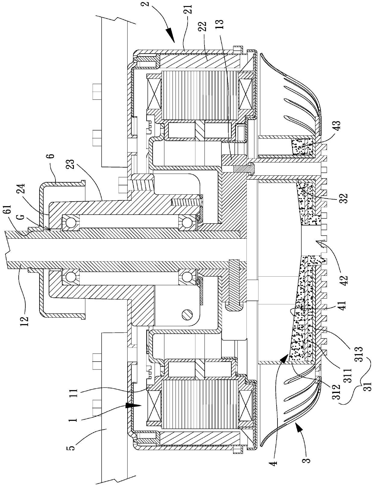
[0053] Please refer to Figure 5 , which is the fourth embodiment of the ceiling fan of the present invention, the fourth embodiment of the present invention is substantially the same as the above-mentioned third embodiment, the main difference is that the fourth embodiment of the present invention has the drainage structure 4 and the water guide part 4', the drainage hole 42 of the drainage structure 4 communicates with the lowest position of the inclined part 41, the drainage hole 42 of the water guiding part 4' communicates with the lowest position of the inclined part 41, and the ceiling fan is simultaneously provided with the drainage The structure 4 and the water guide 4'; in this way, it can also ensure that the water vapor in the electrical box 31 can be removed to prevent the phenomenon of water accumulation inside the ceiling fan, thereby having a better drainage effect.

[0054] To sum up, the ceiling fan of the present invention utilizes the design that the drainag...


PUM


Abstract

A ceiling fan is used for solving the problem that accumulated water in an existing ceiling fan cannot be drained. The ceiling fan comprises: a stator which is provided with a winding assembly and a shaft rod; a rotor rotatably combined with the periphery of the shaft rod; a base combined with the stator; a drainage structure arranged on the base, wherein the drainage structure is provided with aninclined part and a drainage hole, and the drainage hole is communicated with the lowest position of the inclined part; and the plurality of fan blades arranged on the rotor.

Description

technical field [0001] The invention relates to a ceiling fan, in particular to a ceiling fan with a drainage structure. Background technique [0002] Ceiling fans have been widely used by the public because they do not occupy ground space and have a good air disturbance effect. Existing ceiling fans have a stator, a rotor and multiple fan blades. The stator is provided with a shaft, the rotor is rotatably combined with the outer periphery of the shaft, the rotor has a hub, and the plurality of fan blades are combined with the hub; the hub of the rotor rotates relative to the shaft of the stator to The plurality of fan blades are driven to rotate synchronously, whereby the plurality of fan blades drive wind to generate airflow. An embodiment similar to the existing ceiling fan has been disclosed in the "Ceiling Fan" patent case of China Taiwan Publication No. I601920. [0003] However, when the existing ceiling fans are suspended on the indoor ceiling, because the ceiling...

Claims


Application Information

Patent Timeline
Patent Type & Authority Patents(China)
IPC IPC(8): F04D25/08F04D29/00
CPCF04D25/088F04D29/002
Inventor 洪银树王嘉暐陈以杰
Owner SUNONWEALTH ELECTRIC MACHINE IND
Why Eureka
Try Eureka