rolling bearing

A technology of rolling bearings and rolling elements, applied in the field of rolling bearings, can solve problems such as reduced service life

Active Publication Date: 2022-06-07
AB SKF
View PDF13 Cites 0 Cited by
  • Summary
  • Abstract
  • Description
  • Claims
  • Application Information

AI Technical Summary

Problems solved by technology

The service life of the bearing or individual components may therefore be reduced

Method used


Image

  • rolling bearing

Examples


Embodiment Construction

[0042] Below, identical or functionally equivalent elements are represented by the same drawing marks.

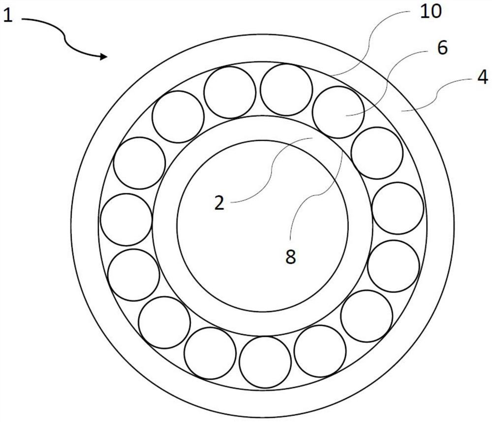
[0043] at Figure 1, the rolling bearing 1 is drawn in a very simplified profile. Rolling bearings 1 consist of an inner ring 2 and an outer ring 4. The rolling element 6 may be arranged rotatably between these two circles 2 and 4. Here, the rolling element 6 runs against the outer surface 8 of the inner ring 2 and the inner surface 10 of the outer ring 4 (run). In order to protect raceways 8, 10 and rolling elements 6 from wear, these (constituent parts) are each provided with a coating. Here, the coating of the rolling element 6 may have a greater hardness than the coating of raceway 8, 10. The coating of the rolling element 6 may, for example, be baked blue (bluing).

[0044] Circle raceways 8, 10 (preferably the entire circle 2, 4) is provided with a phosphate coating (phosphate coating), in order to provide a sliding layer for rolling elements 6. In particular, the coating ...


PUM

PropertyMeasurementUnit
thicknessaaaaaaaaaa
thicknessaaaaaaaaaa

Abstract

A rolling bearing (1) is disclosed, comprising an inner ring (2) and an outer ring (4), rolling elements (6) being rotatably arranged between the inner ring (2) and the outer ring (4) Between, wherein the raceway (8) of the inner ring (2) and / or the raceway (10) of the outer ring (4) are at least partially coated with a first coating, the rolling elements (6) At least partly coated with a second coating, said first coating and said second coating being different from each other, ie preferably phosphate coating and bluing.

Description

Technical field [0001] The present invention relates to a rolling bearing according to the pre-sequence portion of the present patent scheme 1, comprising (such) a rolling bearing, comprising an inner ring and an outer ring, a rolling element may be rotated between the inner ring and the outer ring. Background [0002] In rolling bearings, the surface of the ring (or raceway) and the surface of the rolling element are often coated to achieve surface protection or the improved function of the rolling bearing. [0003] For example, the surface (especially the surface of the rolling element) may be subject to a black oxidation treatment (such as baked blue) in order to produce a multifunctional layer that protects the rolling element. This often occurs in relation to bearings that are completely baked blue. Roasted blue provides a reduction in damage mechanisms, such as corrosion protection on the surface. In addition, roasted blue improves the running-in characteristics of the surf...

Claims


Application Information

Patent Timeline
Patent Type & Authority Patents(China)
IPC IPC(8): F16C33/58F16C33/64F16C33/32F16C33/34
CPCF16C33/58F16C33/64F16C33/32F16C33/34F16C2223/30F16C19/06F16C33/30F16C33/62F16C2206/02F16C19/26
Inventor 蒂洛·冯·施莱尼茨
Owner AB SKF
Why Eureka
Try Eureka