Smelting electric furnace
A technology of electric furnace and furnace body, which is applied in the field of smelting electric furnace, which can solve the problems of high risk of smelting solution overflow, increase the height difference between electrode holes and liquid outlets, etc., and achieve the effects of improving product quality, expanding storage capacity, and improving stability
- Summary
- Abstract
- Description
- Claims
- Application Information
AI Technical Summary
Problems solved by technology
Method used
Image

Examples
Embodiment Construction
[0021] Specific embodiments of the present invention will be described in detail below in conjunction with the accompanying drawings. It should be understood that the specific embodiments described here are only used to illustrate and explain the present invention, and are not intended to limit the present invention.
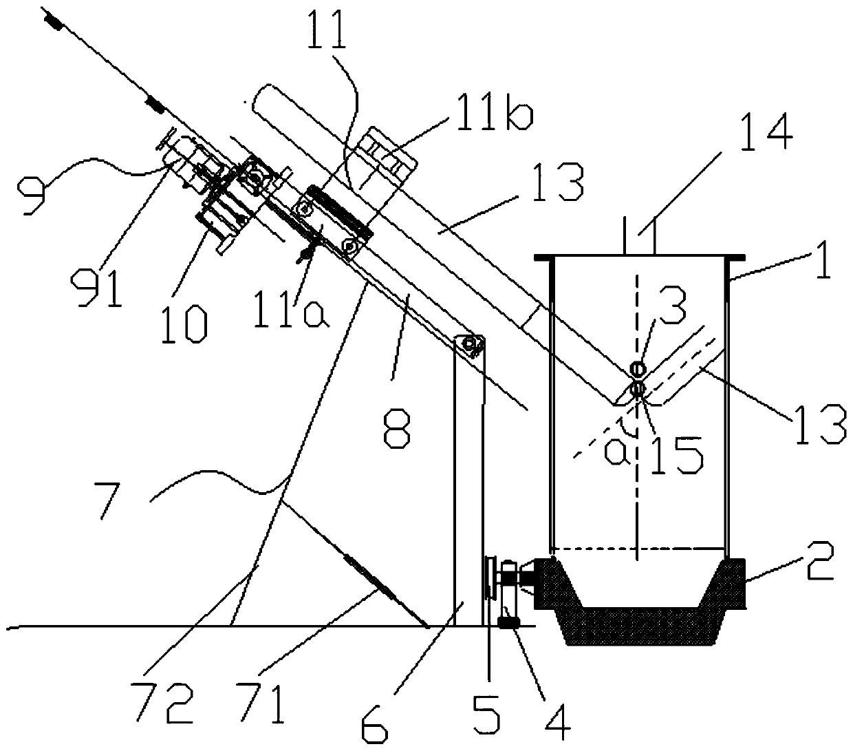
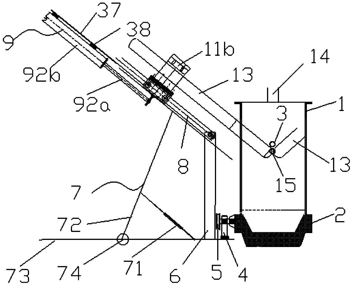
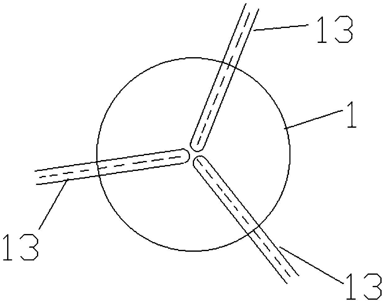
[0022] The invention provides a smelting electric furnace, such as figure 1 and 2 As shown, the electric smelting furnace includes a furnace body 1 and a plurality of electrodes 13, the top of the furnace body 1 is provided with a material inlet 14, and the side wall of the furnace body 1 is provided with a liquid outlet 3 and a plurality of electrodes A plurality of the electrode holes are arranged at the same height and above the liquid outlet 3, and a plurality of the electrodes 13 are arranged to respectively pass through the plurality of electrode holes and extend obliquely downward to the The furnace body 1 gathers to form a high-temperature digestion zo...
PUM
 Abstract
Description
Claims
Application Information
 - R&D
- Intellectual Property
- Life Sciences
- Materials
- Tech Scout
- Unparalleled Data Quality
- Higher Quality Content
- 60% Fewer Hallucinations
Browse by: Latest US Patents, China's latest patents, Technical Efficacy Thesaurus, Application Domain, Technology Topic, Popular Technical Reports.
© 2025 PatSnap. All rights reserved.Legal|Privacy policy|Modern Slavery Act Transparency Statement|Sitemap|About US| Contact US: help@patsnap.com