Projector optical machine test system and method

A test system and test method technology, applied in optical instrument testing, machine/structural component testing, instruments, etc., can solve problems such as manual operation, low intelligence, inconvenience for operators, recording errors, etc., to improve intelligence the effect of

Active Publication Date: 2019-07-19
GOERTEK OPTICAL TECH CO LTD
View PDF8 Cites 4 Cited by
  • Summary
  • Abstract
  • Description
  • Claims
  • Application Information

AI Technical Summary

Problems solved by technology

However, this test method needs to manually read the data and record it, import the recorded data to the PC, and then burn it to the programmer through the PC, which requires manual operation, low intelligence, inconvenient for operators, and easy There is a problem with recording errors

Method used


Image

  • Projector optical machine test system and method
  • Projector optical machine test system and method
  • Projector optical machine test system and method

Examples


Embodiment Construction

[0044] The following will clearly and completely describe the technical solutions in the embodiments of the present invention with reference to the accompanying drawings in the embodiments of the present invention. Obviously, the described embodiments are only part of the embodiments of the present invention, not all of them. Based on the embodiments of the present invention, all other embodiments obtained by persons of ordinary skill in the art without creative efforts fall within the protection scope of the present invention.

[0045] It should be noted that if there is a directional indication (such as up, down, left, right, front, back...) in the embodiment of the present invention, the directional indication is only used to explain the position in a certain posture (as shown in the accompanying drawing). If the specific posture changes, the directional indication will also change accordingly.

[0046] In addition, if there are descriptions involving "first", "second" and ...


PUM


Abstract

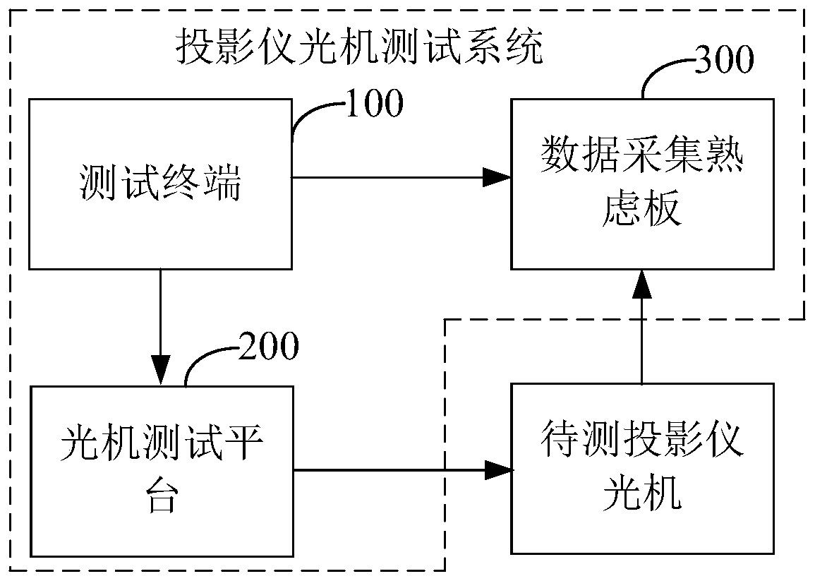
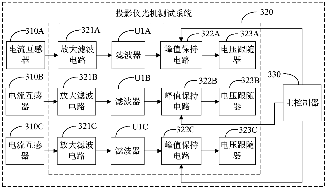
The invention discloses a projector optical machine test system and method. The projector optical machine test system comprises a test terminal, an optical machine test platform and a data acquisitionand burning plate; the test terminal is configured to output a current control signal while testing; the optical machine test platform is configured to place a projector optical machine to be tested,and drive the projector optical machine to be tested to work according to the current control signal; the data acquisition and burning plate is configured to obtain the current brightness value of the projector optical machine to be tested and the current value of red, green and blue LEDs in the projector optical machine under the current brightness, and determine that the current of each LED isset correctly when the current bright values of the red, green and blue LEDs are matched with the pre-set brightness value; and the test terminal is also configured to record the current value of thered, green and blue LEDs under the current brightness, and burn into the storage of the projector optical machine to be tested through the data acquisition and burning plate. By means of the projectoroptical machine test system and method in the invention, the test intelligence of the projector optical machine is improved; manual operation is unnecessary; and the problems that the projector optical machine is low in test intelligence, inconvenient to operate by an operator and easy to have clerical error can be solved.

Description

technical field [0001] The invention relates to the technical field of electronic circuits, in particular to an optical-mechanical testing system and method for a projector. Background technique [0002] At present, the test method of the optical machine of the projector is usually a scheme of sampling current probe + oscilloscope + PC + burner. However, this test method needs to manually read the data and record it, import the recorded data to the PC, and then burn it to the programmer through the PC, which requires manual operation, low intelligence, inconvenient for operators, and easy There is a problem with logging errors. Contents of the invention [0003] The main purpose of the present invention is to provide a projector optical-mechanical testing system and method, aiming at improving the intelligence of the projector optical-mechanical testing. [0004] In order to achieve the above object, the present invention proposes a projector optical-mechanical testing s...

Claims


Application Information

Patent Timeline
Patent Type & Authority Applications(China)
IPC IPC(8): G01M11/00
CPCG01M11/00
Inventor 高文刚
Owner GOERTEK OPTICAL TECH CO LTD
Why Eureka
Try Eureka