Eureka AIR delivers breakthrough ideas for toughest innovation challenges, trusted by R&D personnel around the world.

A safety helmet random collision intelligent testing equipment

A test equipment and helmet technology, which is applied in the field of intelligent test equipment, can solve problems such as poor test results, and achieve the effects of improving pressure measurement results, reducing work, and realizing guidance and fixation

Active Publication Date: 2021-09-03
深圳艾科思实业有限公司
View PDF9 Cites 0 Cited by
  • Summary
  • Abstract
  • Description
  • Claims
  • Application Information

AI Technical Summary

Problems solved by technology

[0004] In order to overcome the shortcomings of the existing anti-pressure equipment, the test effect is poor, and technicians are required to operate, the technical problem of the present invention is: to provide a random collision intelligent test equipment for safety helmets that can realize automatic testing and good test results

Method used


Image

  • A safety helmet random collision intelligent testing equipment
  • A safety helmet random collision intelligent testing equipment
  • A safety helmet random collision intelligent testing equipment

Examples


Embodiment 1

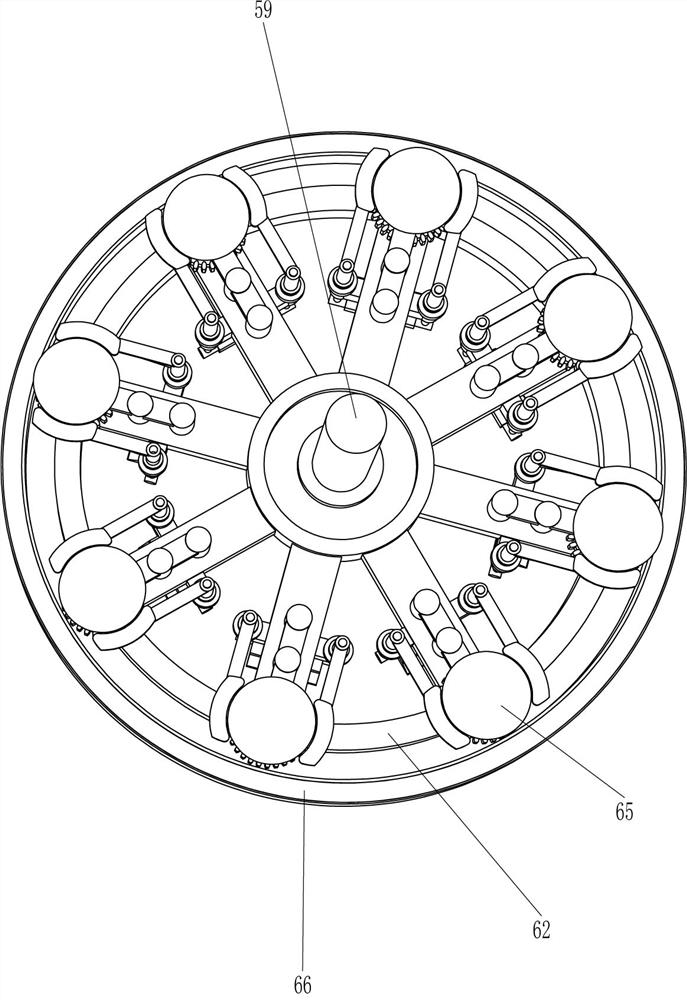
[0084] A safety helmet random collision intelligent test equipment, such as figure 1 As shown, it includes a base 1, a mounting frame 2, a bracket 3, a driving mechanism 4, a clutch mechanism 5, a rotating mechanism 6 and an extruding mechanism 7. The left side of the base 1 is provided with a mounting frame 2, and the right front side of the base 1 is provided with a bracket 3. , a drive mechanism 4 is provided in the middle of the base 1, a clutch mechanism 5 is provided between the base 1, the installation frame 2 and the drive mechanism 4, a rotation mechanism 6 is connected between the clutch mechanism 5 and the installation frame 2, and the connection between the base 1 and the clutch mechanism 5 There is an extruding mechanism 7 connected between them.

[0085] When people need to carry out anti-compression intelligent test on the side of the helmet, the helmet is first placed on the parts of the rotating mechanism 6, and then the driving mechanism 4 is started, and the...

Embodiment 2

[0087] On the basis of Example 1, such as Figure 1-6 As shown, the driving mechanism 4 includes a reduction motor 41 and a rotating rod 42 , the reduction motor 41 is provided in the middle of the base 1 , and the rotation rod 42 is provided on the output shaft of the reduction motor 41 .

[0088] When people need to carry out anti-compression intelligent test on the side of the helmet, the helmet is first placed on the parts of the rotating mechanism 6, then the deceleration motor 41 is started, and the output shaft of the deceleration motor 41 rotates to drive the rotating rod 42 to rotate, and then drives the parts of the rotating mechanism 6 Rotate with the helmet, and close the reduction motor 41 after completion.

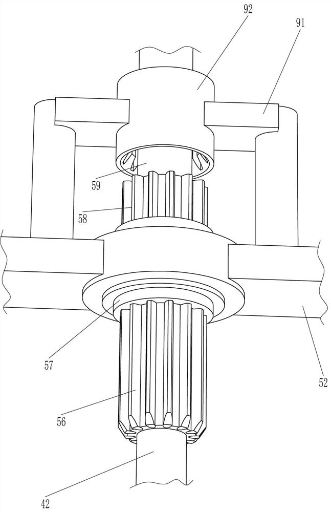
[0089] The clutch mechanism 5 includes a first guide rod 51, a guide plate 52, a first spring 53, a connecting plate 54, a pedal 55, a first gear rod 56, a first ring gear 57, a second gear rod 58 and a drive rod 59, and the base 1 First guide rods 51 are co...


PUM


Abstract

The invention relates to an intelligent testing device, in particular to an intelligent testing device for safety helmet random collision. The technical problem of the present invention is to provide an intelligent safety helmet random collision testing device capable of automatic testing and good testing effect. The technical embodiment of the present invention is: a safety helmet random collision intelligent testing equipment, including a base and a mounting frame, a mounting frame is provided on one side of the base; a bracket is provided on one side of the base; a driving mechanism is provided in the middle of the base. Mechanism; a clutch mechanism, a clutch mechanism is arranged between the base, the installation frame and the driving mechanism; a rotation mechanism, a rotation mechanism is connected between the clutch mechanism and the installation frame. Through the cooperation among the driving mechanism, the clutch mechanism, the rotating mechanism and the extrusion mechanism, the intelligent test of the helmet can be realized, and the pressure measurement effect can be improved by randomly testing the parts of the helmet.

Description

technical field [0001] The invention relates to an intelligent testing device, in particular to an intelligent testing device for safety helmet random collision. Background technique [0002] A helmet is a device to protect the head, a hat worn by soldiers during training and combat, and an indispensable tool in people's transportation. It is mostly semicircular and mainly consists of three parts: shell, lining and suspension device. The shells are made of special steel, fiberglass, reinforced plastics, leather, nylon and other materials to resist damage to the head by warheads, shrapnel and other hitting objects. [0003] Therefore, the helmet anti-compression test is very important. Now the anti-compression test only uses some anti-compression equipment to hit the helmet. The test effect is poor and requires technicians to operate. Therefore, a safety helmet that can realize automatic testing and test results is now developed. Side pressure intelligent test device. Con...

Claims


Application Information

Patent Timeline
Patent Type & Authority Patents(China)
IPC IPC(8): G01M7/08
CPCG01M7/08
Inventor 王淑萍
Owner 深圳艾科思实业有限公司
Why Eureka
Eureka Blog
Learn More