Laser radar combined calibration method and device

A laser radar and joint calibration technology, which is applied in radio wave measurement systems, instruments, etc., can solve the problems of low calibration accuracy and achieve good robustness, improved calibration accuracy, and strong anti-interference effects

Active Publication Date: 2019-07-19
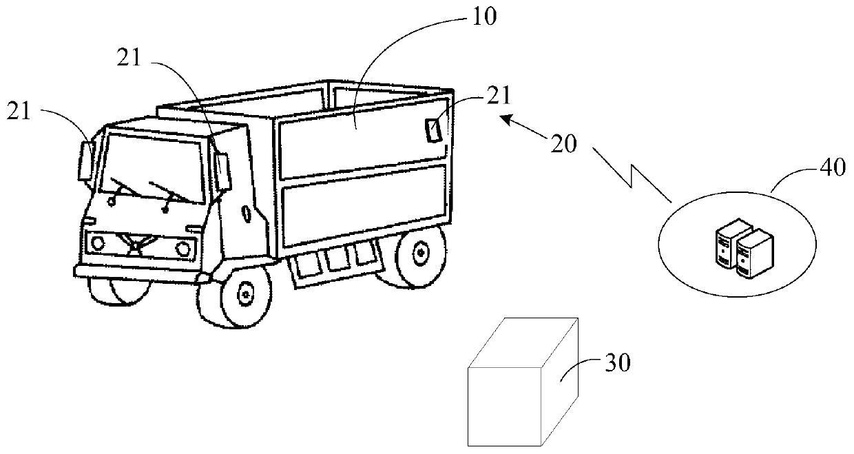
杭州飞步科技有限公司
View PDF7 Cites 26 Cited by
  • Summary
  • Abstract
  • Description
  • Claims
  • Application Information

AI Technical Summary

Problems solved by technology

[0005] This application provides a laser radar joint calibration method and device to solve the techn

Method used


Image

  • Laser radar combined calibration method and device
  • Laser radar combined calibration method and device
  • Laser radar combined calibration method and device

Examples


Embodiment Construction

[0034] Reference will now be made in detail to the exemplary embodiments, examples of which are illustrated in the accompanying drawings. When the following description refers to the accompanying drawings, the same numerals in different drawings refer to the same or similar elements unless otherwise indicated. The implementations described in the following exemplary examples do not represent all implementations consistent with the present disclosure. Rather, they are merely examples of apparatuses and methods consistent with aspects of the present disclosure as recited in the appended claims.

[0035] Furthermore, descriptions with reference to the terms "one embodiment," "some embodiments," "example," "specific examples," or "some examples" mean that a specific feature, structure, material, or A feature is included in at least one embodiment or example of the invention. In this specification, the schematic representations of the above terms are not necessarily directed to t...


PUM


Abstract

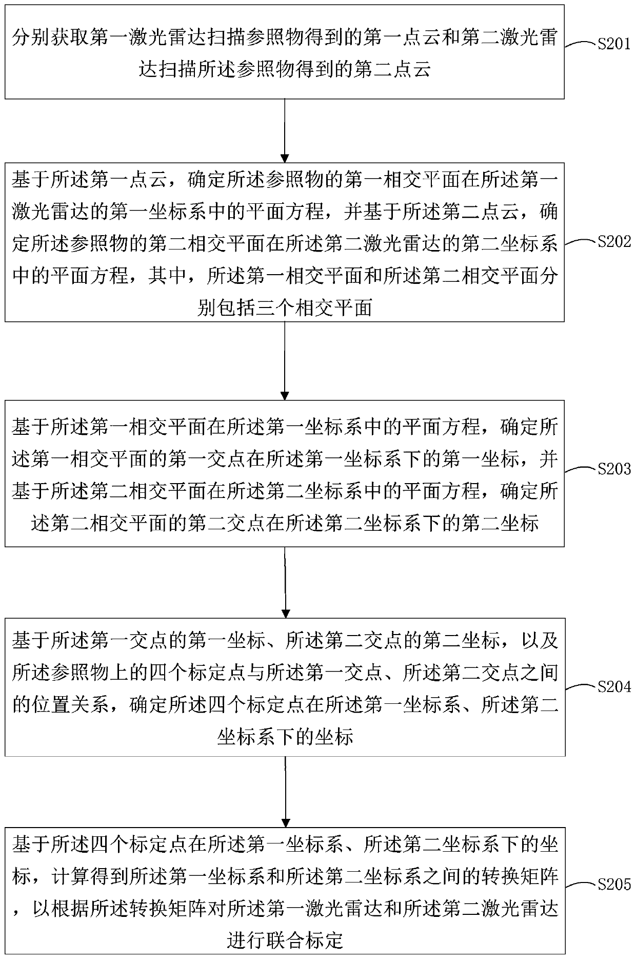
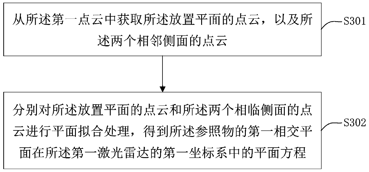
The embodiment of the invention provides a laser radar combined calibration method and device. The laser radar combined calibration method comprises the steps: first point cloud obtained by a first laser radar scanning reference object and second point cloud obtained by a second laser radar scanning reference object are obtained correspondingly; based on the first point cloud, a plane equation ofthe first intersection plane of the reference objects in a first coordinate system of a first laser radar is determined, and according to the plane equation, coordinates of four calibration points inthe first coordinate system are determined, wherein the four calibration points are not coplanar; based on the second point cloud, coordinates of the four calibration points in a second coordinate system of a second laser radar are determined as well; and based on the coordinates of the four calibration points in the first coordinate system and the second coordinate system, a conversion matrix between the first coordinate system and the second coordinate system is calculated to conduct combined calibration on the first laser radar and the second laser radar according to the conversion matrix,and thus the calibration accuracy of laser radar combined calibration is greatly improved.

Description

technical field [0001] The present application relates to the field of unmanned driving technology, and in particular to a lidar joint calibration method and device. Background technique [0002] LiDAR is widely used in environment perception and autonomous navigation in unmanned driving. [0003] Due to the large size of the truck and the occlusion of the cargo, one laser radar cannot completely obtain the 360-degree scene information around the truck. Therefore, it is necessary to install multiple laser radars at different positions of the truck to detect obstacles and obtain environmental information. In order to fuse the environmental information obtained by multiple lidars, joint calibration between multiple lidars is required, that is, the coordinates of multiple lidars are unified into the same coordinate system. [0004] In the prior art, the point cloud registration of two laser radars is generally performed based on feature points, that is, registration is perform...

Claims


Application Information

Patent Timeline
IPC IPC(8): G01S7/497
CPCG01S7/497
Inventor 黄玉辉钱炜
Owner 杭州飞步科技有限公司
Why Eureka
Try Eureka